Continue to Site

Eng-Tips is the largest engineering community on the Internet

Intelligent Work Forums for Engineering Professionals

  • Congratulations GregLocock on being selected by the Eng-Tips community for having the most helpful posts in the forums last week. Way to Go!

10x10 Timber Beam Sagging in century old home 4

Status
Not open for further replies.

N3M4N

Structural
Aug 15, 2018
24
Hi all,

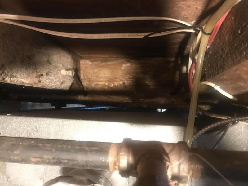
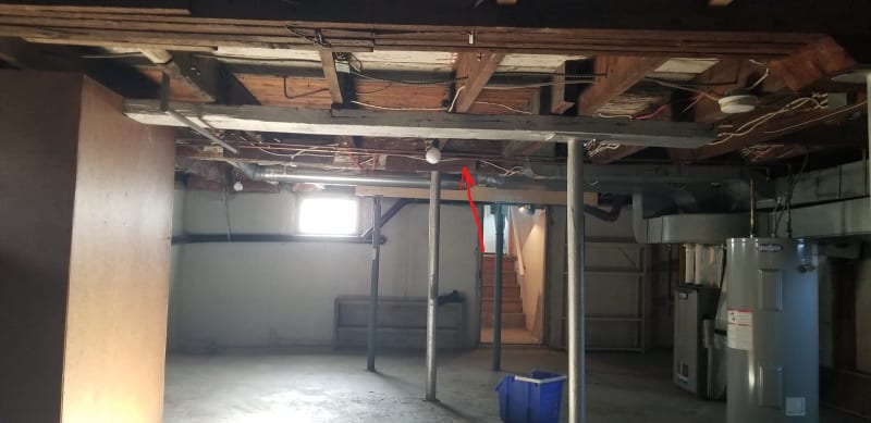
I am looking to find a viable solution to fix a cracked beam that is sagging. The issue is that there max 2 inch clearance between the beam and the furnace below, which is also the lowe point of the beam. see below
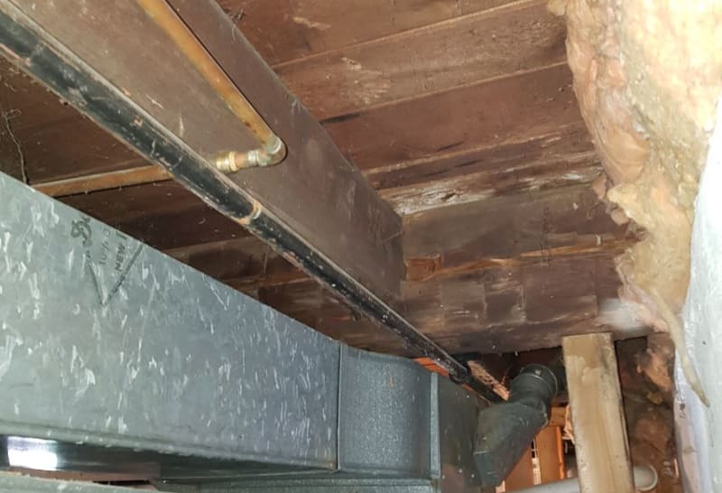
IMG_3_bsorrj.jpg


My proposed solution is to add 1/4" thick steel angle (i.e. lintel) below beam and support it at each end. The steel angle is the only thig I can think of to be able to slide between the beam and furnace, see below.
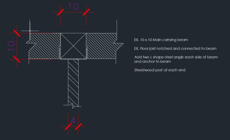
beam_detail_perilj.jpg


Any suggestions?

Thanks in advance.
 
Replies continue below

Recommended for you

What is the connection detail of the floor joists to the beam? How do you "notch" the floor joists, to fit the angles, without detaching the joists from the 10 x 10 beam?
If you can put one new column on one side of the ductwork do you really need to install the angles? reducing the beam span may be enough to avoid "fixing" the beam.
If you can put one new column on one side, can you put a new column on each side of the ductwork and don't use the angles?

 
The beam and the joist are notched, the joists run through the beam. Hope the image below clears it up.

175861106_926821337899074_2988329570546782343_n_sbipol.jpg
 
Two acrows?

Remember - More details = better answers
Also: If you get a response it's polite to respond to it.
 
Looks to me like this is the old timber frame connection where a slot was cut partially into the main beam to provide the "beam hanger". The joists do not run through the beam.

Looks like crack in beam is located at the bottom of the notched end joist beam seat. Is the second photo of the opposite side of the beam? Crack looks smaller on that side, if so.

Think your idea of a steel post with saddle on either side is a good one. Is the floor slab thick enough to carry the post load. In a house that old, it might be pretty thin - depression era cheap?

Could do pier block with adjustable post (Simpson Strong Tie) and 6x6 post. Then you could jack upwards to take out sag.
 
@Sawbux
Really like your idea of pier block with adjustable post. The challenge will be fitting the steel angles under the beam, it might interfere with the joist.

Is it a bad idea to hire a contractor and remove the ductwork first? doing this will cost me a lot more but not sure if there is a way around it.

@PEinc
My concern is that the crack in the beam is too wide, and beam has sagged. if I jack it up and place post on either side of the furnace, I am afraid the beam might fail.

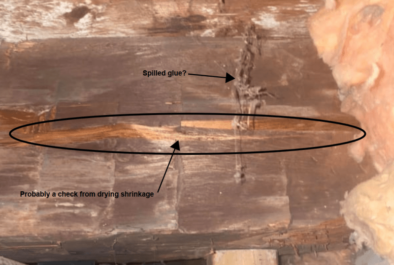
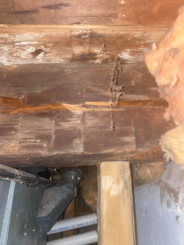
does this look like shrinkage crack? should I be alarmed? see close up picture below.

Beam_cracked_temporary_4x4_support_posts_due_to_safety_concern_ophliv.jpg


1_j8yrv5.jpg
 
Does the crack go all the way through? It could just be typical checking of old growth timber. But the sagging is potentially a bigger concern. And jacking it back up may cause more issues than it fixes. Jacking the beam could cause finish damage above the beam if the sagging has been in place for a while. If it is new sagging, then what has changed to cause it? Higher moisture content of the area? Change in loading? If it isn't new, then be sure the fix is absolutely necessary before going forward with it.
 
Had a similar issue once, we used a channel flange down so that there was no notching needed.
We added two posts and then gradually tightened them over about 9 months. We never did get them jacked all of the way up, it became obvious that we didn't need it since it had always sagged some.

= = = = = = = = = = = = = = = = = = = =
P.E. Metallurgy, consulting work welcomed
 
EdStainless said:
Had a similar issue once, we used a channel flange down so that there was no notching needed.

I am having a hard time visualizing how you installed the channel flange and avoided running into the joists? Now my issue is that i don't have much room under the beam because of the furnace, prob 2 inches.

jayrod12 said:
Does the crack go all the way through?

The crack doesn't go all the way through the beam but its fairly deep and wide.

jayrod12 said:
If it is new sagging, then what has changed to cause it?

Its hard to say, I know next door to us they are building a 4 storey high condo, they had drill rigs for deep foundation, lots of shaking and vibration. Contractor excavated massive hole prob 30+ feet (underground parking). They placed shoring wall around and dewatering for months.
 
If it were new sagging, you would likely have damaged finishes above this area, especially if it is brittle finishes like drywall and plaster. If nothing new has surfaced in terms of finish damage, then it's quite possible that the sagging is existing.

Now, even if the sagging is existing doesn't mean there isn't concern. But my point is more in regards to jacking the beam back up. I wouldn't do that if there is currently no damage to the finishes above, as jacking the beam would quite likely cause finish damage.
 
So what does this two angles either side of beam look like? You have to transfer a good portion of the bottom side fiber tension in the beam to the angles in order for them to function as part of the beam. (Like tension rebar in a concrete beam), otherwise you just have two angles attached to a beam. How do you intend to make that transfer possible?
 
1503-44 said:
So what does this two angles either side of beam look like?

Will have to pre drill the steel and anchor it to the beam using lag screws.

 
I thought it might be something like that. I'm not sure how effective that will be. Drilling will remove a lot of wood from the beam tension fiber area. The discontinuiety introduced will tend to divert tension in the wood to go around the holes. Wood tension next to the screw is zero. What tension can be transferred to the screw when there is none there to transfer. Then looking at a hole that is essentially getting pulled into a longer oval shape, how will tension in the wood get to the screw? The wood is trying to pull away from the screw on each side. It seems to me that the only mechanism available to accomplish any stress transfer might be friction between the angles and wood beam surface, as you have no other bonding agent, such as cement bonding to rebar provides. Can lag screws apply enough force to the angles to develop enough friction to pick up the wood's fiber stress? How much? It would seem that glueing the angles to the beam would be better, but I have no idea if that would work either.

I've thought of using a tension bar placed just under a beam to try to make it work like a prestressed bar in a prestressed concrete beam, but located just next to, rather than inside the beam itself. You could then theoretically get enough tension in the rod to force the neutral axis down and even carry all the beams tension stress, leaving only compressive stress across the wood section. But then you have to anchor the rod to the beam and, with that high a rod tension load, that wouldn't be easy either. Maybe you could pass the rod through holes in clip angles located every 2 ft or so along the beam, screw the clips to the wood, stress the rod, then tack weld the rod to the clips. I still think you'd need some pretty hefty screws though.
 
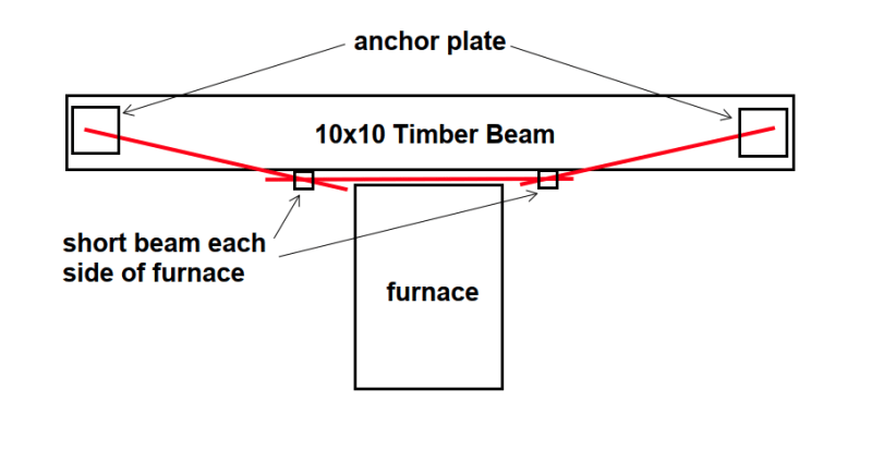
I suggest using threaded rods as shown in red each side of the timber beam. The rods at the two ends could be attached with steel plates fastened with glulam rivets. The sloping rods put an upward force on the short beams below the 10x10. The horizontal rod would be tightened with nuts and anchored with a lock nut. Sloping rods would need to be drilled through existing joists.

image_zjjddo.png


BA
 
1503-44 said:
I can't see the advantage of sloped rods.

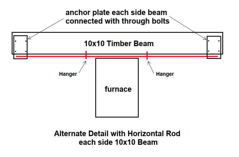
I believe that sloping rods makes the connections to the beam a little easier, by riveting anchor plates to the sides of the beam instead of the bottom. Sloping rods provide a vertical reaction to the beam each side of the furnace, which a horizontal rod does not provide. One full length rod is probably not feasible because of basement clearances, but three rods would be more manageable.

If the end rods are horizontal, the connection to the beam could be a plate riveted to the underside of the beam, but the connection to the rods would be difficult. Could use a plate each side of the beam, but that would have to be designed as a moment connection to the beam, always difficult with timber.

BA
 
This could work if there is sufficient clearance to get the rods in place. Otherwise, they would have to be spliced.

image_rfo21e.png


BA
 
I was thinking the sloped rod would develop a very high tension because the distance to a supposed neutral axis decreases, as would happen in prestressed concrete design, no? But since it is not continuously bonded, you may be right in it acting more like a truss member. In that case the sloped rods load is set by the tension in the horizontal rod, and the beam starts to pick up the moment as we move from there toward the ends.
 
N3M4N,

Could the OP place arrows on the pictures showing the location and length of the crack in the Beam, as I can not see this crack?

Is it also true that the crack does not go thru the entire depth/thickness of the beam?

Maybe my eyes are so bad that I can no longer read these photographs, but it seems to me that we are getting a lot of terrible photos.


Jim

 
I interpreted the crack as shown below. The crack may not affect strength too much, but wouldn't hurt to give the beam a little help.

image_qfw9st.png


BA
 
Status
Not open for further replies.

Part and Inventory Search

Sponsor