Continue to Site

Eng-Tips is the largest engineering community on the Internet

Intelligent Work Forums for Engineering Professionals

  • Congratulations KootK on being selected by the Eng-Tips community for having the most helpful posts in the forums last week. Way to Go!

3 phase generator with amperage on ground

Status
Not open for further replies.

Duckman25

Electrical
Oct 28, 2023
5
We have a 3 phase 480 v 60 kW generator that parallels the electric utility at 60 hz. The purpose of the generator is to generate electricity instead of buying it from the utility. When the paralleling switch closes, we see the the amperage on each leg climb quickly (up to 200 amps prior to us giving the shut down command) but the kW stays at less than 10 kW. We have confirmed that the amperage observed is correct (using an amp clamp). We have also found that the ground has about 70 amps during that time. at 200 amps on each leg, we would expect much more power (kW) would be greater. Trying to figure out what is causing this condition.
 
Replies continue below

Recommended for you

How do you parallel generator with the utility? If it is done without checking the voltage, frequency and phase angle matching, you are likely to have problems like those you are experiencing.
The large current is due to big voltage mismatch and most of it due to reactive power I suppose. Low kW suggests that the frequency of the generator is close to that of the utility at the time of paralleling.
If you can vary the generator AVR, you should be able to reduce the current. Whether you need to increase or decrease the excitation current to the generator field depends on what is the power factor of the generator current. If the power factor is leading, you need to increase the field current.
Using the generator governor, you should be able to increase the generator kW output.

R Raghunath
 
Paralleling 101:
Your voltage is set too high and you are exporting reactive power.
By ground current you probably mean neutral current:
Three possible causes:
1. The voltage is high or low on one utility phase.
2. There is a set of voltage regulators upstream of you on the utility system and the phase angles are not even.
3. Something in your plant or nearby is generating a lot of third harmonics.​


--------------------
Ohm's law
Not just a good idea;
It's the LAW!
 
By the way, If your utility KWHr meter is at the default setting, you will be charged for any energy that you export. You may be charged a PF penalty for excess reactive power exported.
Check your power bills.
Let me guess; You didn't tell your utility about this connection.

--------------------
Ohm's law
Not just a good idea;
It's the LAW!
 
We have software that syncs our unit to the grid. It must match freq, phase and voltage before it gives the command to close the switch. We do not run a neutral, it is truly a ground, and yes, we complied with connection to the local utility in regards to interconnection requirements (reverse power, etc., protection). Based on the responses, I am thinking that the AVR on the genny is not working properly.
 
Also, is your governor set for droop or isochronous mode? If in droop the generator will not take load.
 
The generator set needs commissioning.

60 kw is very small to have the controls and engineering required to operate mains parallel.

Do you have to have permission from your electrical utility to do this?

The costs and hassle of this usually dissuade small generators from paralleling unless the utility has a procedure for small generators.


Also, is your governor set for droop or isochronous mode? If in droop the generator will not take load.
Got this mostly backwards.
Droop allows the set to track the inevitable small frequency changes of the grid.
Isochronous is only for the swing set.

Thanks for the added information.
The added information points to an issue with PF control.
PF control on the wrong setting or in the wrong mode may cause issues with reactive current.
There is always confusion between "ground" and "neutral" between line people and plant people.
For NEC installations, there are strict definitions for both ground and neutral.
Power line people use the same conductor for both ground and neutral.
Power line people tend to use the term "ground" for both ground and neutral conductors.
With grounded generator windings, and the absence of a neutral conductor, the grounding conductor will also act as a neutral conductor.
70 Amps of true ground current may be a sign of impending, rapid generator failure.
If you are a long way from the substation and if the distribution line has distributed single phase loads, or if there are one or more banks of voltage regulators on the distribution circuit then 70 Amps of neutral/ground current is often a sign of a) a voltage difference on one phase; b) a phase angle error on one phase; c) usually both.
This is something that you probably have to live with.
Normal load = 12 Amps = 10 Kw (12.5KVA ?)
Generator capacity 72 Amps = 60 KVA
Loading = 200 Amps = 166 KVA
CHECK YOUR POWER FACTOR CONTROL SETTINGS
Once you get your voltage/current under control the neutral/ground current should drop to under 5 Amps.
If the neutral/ground current doesn't drop significantly, watch for smoke.

--------------------
Ohm's law
Not just a good idea;
It's the LAW!
 
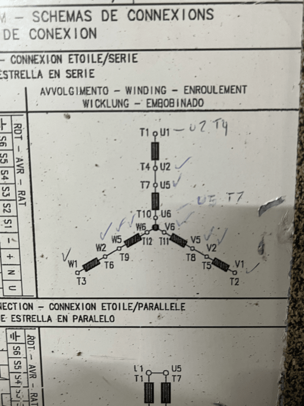
Thanks for everyone's comments. The generator is rated for 400 kW - not 60 kW. We have permission from the utility - not our first rodeo with them as we have implemented an SEL protection scheme with a variety of protections and sensing on the mains. Here is a pic of how the genny is connected.
winding_lwy46t.png
 
What do you mean by ground current and where are you measuring it?

Did you swap the connections in U phase? If you did, change it back as per nameplate.

Muthu
 
Good question on the ground - I will need to double check. RE nameplate, the handwritten notes are based on how the wiring was labeled by the folks that cleaned/reconditioned the unit.
 
Who marked up your nameplate? Was it the reconditioners? Are those old marks left over from a previous installation? I hate it when people mark up diagrams like this.
 
We asked our electrician to double check the wiring connections from the generator, AVR and the monitoring system (measures through CTs and VTs). He found that some of the wires on the generator connections (as seen in the pic) were duplicated.
 
If you are measuring 480 Volts line to line on all three phases, the connections are good, the numbers not so good.
Equal currents (200 Amps) on all three phases indicates that the connections are correct. (unless there is something that you have not told us).
How far, in miles, is your installation from the substation that feeds you?
There are strong indications that you are either over-excited or under-excited.
You may have a reversed connection in your control circuit or a reversed CT in your PF measuring circuit.
You may try connecting a voltmeter to the AVR output and check the field voltage before paralleling and after paralleling.
See if the excitation voltage increases or decreases when you parallel.

--------------------
Ohm's law
Not just a good idea;
It's the LAW!
 
Status
Not open for further replies.

Part and Inventory Search

Sponsor