Eng-Tips is the largest engineering community on the Internet

Intelligent Work Forums for Engineering Professionals

40-ton timber arches collapse in Hickory, NC 35

Status
Not open for further replies.

bugbus

Structural
Aug 14, 2018
498
0
0
AU

Before:
c_v0gdsn.jpg

a_xq7ujk.jpg

b_bjiumg.jpg


After:
3_idudj9.jpg

2_cygatg.jpg

1_scwfo5.jpg
 
Replies continue below

Recommended for you

Electronbelt (Industrial) 19 Jun 22 19:49 said:
...claim they failed while in the air vs the damage in question being the result of the twist and then impact.

Key point.

Edit: The snap back would argue for the damage occurring while the structure was still erect.
 

Out of curiosity, what was the load on it at failure?

Rather than think climate change and the corona virus as science, think of it as the wrath of God. Do you feel any better?

-Dik
 
Sym P. le (Mechanical) 19 Jun 22 19:55 said:
Edit: The snap back would argue for the damage occurring while the structure was still erect.

Very good point if that final position is indeed from a snap back.

dik (Structural) 19 Jun 22 20:24 said:
Out of curiosity, what was the load on it at failure?

I do not see that indicated anywhere in the report. Just that the wind speed around the time of the incident was 18mph with 33mph gusts. The report also states that prior to this the structure: "...had not had high wind loads on it prior to the collapse." See page 6.

A re-occurring theme of the report is that the EOR only modeled a single arch (the upper) for the design/load calculations, and not the two arches tied together as a single structure. It also claims the EOR modeled the guy wires as solid rods in place of cables for the load calculations, possibly influencing the numbers by introducing support in compression. See page 9.
 

As noted earlier in this thread, a possible cause for collapse was due to the geometry. The effects of the cables became negligible, and the forces in them would increase substantially. If the project were mine, I'd likely have modelled it as an upper arch and looked at the effects this would have on the base, including the effects of the geometry. I don't find that to be at fault. I find the reliance on the FEM program to be distressing. For those wind speeds and gusts, I would think the failure wind pressures would be in the order of about 20 psf. The effects of gusts are local and not not on the entire structure at the same time. I didn't like the report. [pipe] [Added] This precludes any dynamic effects of the gustiness.

Rather than think climate change and the corona virus as science, think of it as the wrath of God. Do you feel any better?

-Dik
 
Another source of additional tension on the lower arch cable may have been from the cable crossing the railing on the bridge though the railing may not have much strength to offer resistance and I have not checked the geometry of such an occurrence. IPSO, the structure was so flaky, it fell over. No further assistance required.

Leaning_Bridge_Too_gccl1f.gif


Railing_interference_fqsvia.jpg


Also, a sharp arrow may have pierced the cable.
 
I think everyone who has commented here on this topic would have said:

"Well. That's a VERY unusual design. Since we don't have a lot of history with something like this, let's go real conservative on both design and testing."

I will note that it does not appear that anyone involved in this project said that.


spsalso

 
"Another source of additional tension on the lower arch cable may have been from the cable crossing the railing on the bridge..."

Looking at the first photo posted in this topic, it appears to me that, by the time the cable could have moved to intersect the bridge railing, it was all over.


A strange thing: I just did a search on Bing for "hickory north carolina bridge collapse" in images. There were none for this event. I wonder how that came to be. Google came through.


spsalso
 

A revision to my previous post copied here.

Edit 2 - I see now how the second bolt hole (in the lower cable bracket connection) was utilized. The north side of the timber bracket is bent underneath the debris and would have been provisioned with a second attachment point. My comment on the welding is still in play. It seems like there is ample linear space for a robust weld connection so it brings into question the quality of the weld. Also with regard to the bolt connection, why the slots and did the bolts work themselves loose?
 
I find the comment that someone decided the cables were rods, and could then work in compression pretty hilarious. Just how much compression can you put into a 7/8" rod that is maybe 50' long before it fails and bends? Or bends and fails.


spsalso
 
It is difficult, perhaps impossible, to define exactly which elements failed first, and which were destroyed by the impact, etc. In addition to the crazy looking joints, another thing struck me. A lot of those 'anchor bolts' just pulled cleanly out. The concrete bits seem not to have suffered much, but the bolts popped right out. Straight bolts, no anchorage. Were they chemical anchors or expansion anchors?
 
Edited and corrected again as I misidentified the orientation of the second image.

Birdcaging of the wire rope at the socket may be a clue to the sudden release of tension or indicative of other issues? It appears more pronounced in the south rope which had significant tension failure. Of course when the structure fell, the north rope would go completely slack so perhaps this is evidence of the structure flapping in the wind prior to its collapse or cycling during its short life span.

The upper arch south north cable also exhibits significant birdcaging at the upper socket which would indicate that it was abused as well likely prior to the fall and in another image it is seen to be sharply kinked upwards at the socket so it likely sustained this damage from the fall.

birdcaging_l6aq7g.jpg

Photograph 20

birdcaging.upper_cable_todoae.jpg

Photograph 17 - south cable at the bottom and north cable at the top. The north cable is kinked at the socket but it is not readily apparent in this view.
 
hokie66 (Structural) 20 Jun 22 04:44 said:
Were they chemical anchors or expansion anchors?

Threaded rod epoxied in place but I doubt I can call it accurately from a photo.

So far, all of the anchor bolts I've seen have pulled out of the drilled holes rather than pull up any concrete so it would seem that they did not develop their intended strength. This may be a moot point given the base was entirely more stable than the upper portion.

Anchor_bolts_szuyr0.jpg

Photograph 9
 
Looks like a bunch of stacked shim plates under a relatively thin base plate, with a bit of grout to make it look pretty. Not a base detail to engender confidence.
 
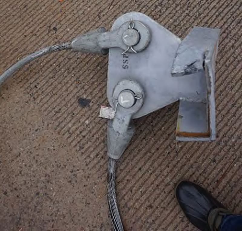
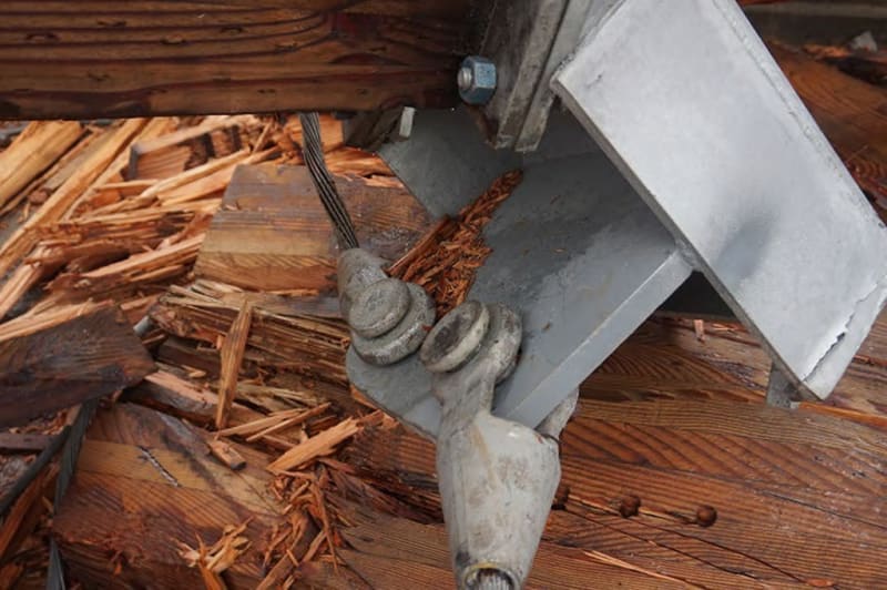
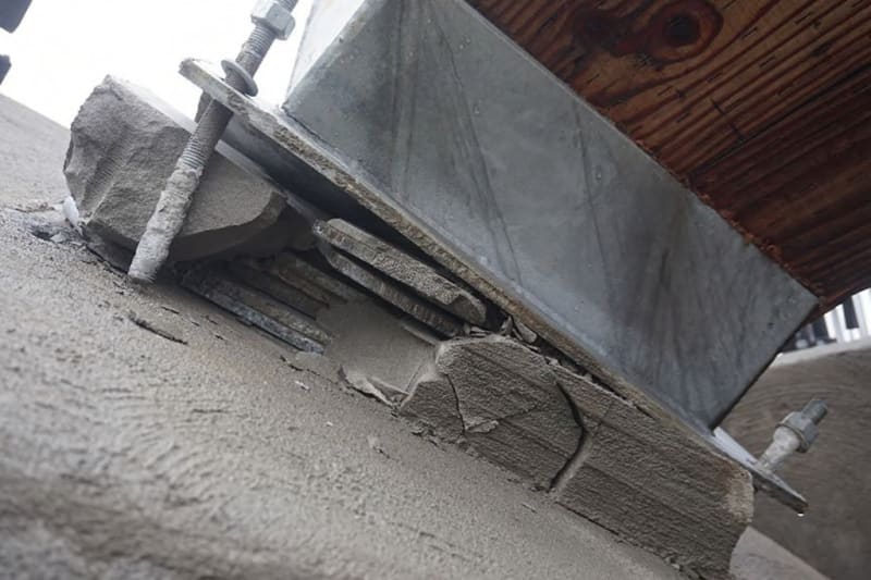
The base plate installation is pretty interesting.

The photo 9 one has some shim plates surrounded by grout to support the base plate. The photo 11 one does not. It is extremely unlikely that the designer would spec two different styles of mounting, one with and one without.

So it appears that the mounting shown in photo 9 came up 3" short (photo 5), and filler was added. I suspect discovery of the need for this modification was made during the physical installation of the arch itself. It does not reek of prior planning.

Study of the photos shows that the hold-down bolts were not an additional 3" longer where the shimming was used. From photo 9, it appears the exposed hold-down bolt was engaged in about 3" of grout and 2 1/2" of concrete.

I have little experience in gluing bolts into concrete, but I do wonder whether the "glued-on stuff" (of about a 2 1/2" length) is concrete dust that was never blown out of the hole.

I question whether the grout is "Structural Grout". Which means that, structurally, it isn't there. So it would contribute nothing to pull out strength for the bolts. In addition, it would provide nothing for lateral movement. As I said, structurally, it isn't there.

I am sympathetic to doing an install, and finding the "bridge" is 3" shorter than the needed span. But this looks incredibly poorly designed. As an experienced electrical worker, with all the knowledge that that implies, I would have at least made the steel shims the full size of the base plate, and cut bolt holes through them. I would have added additional large steel blocks on all four edges to minimize lateral movement of the stack. And I certainly would have used longer bolts.


I am SO looking forward to finding out how this one "solution" turned out to be needed, and was so designed. I note that the Dara Thomas, the investigating forensic professional engineer, made no mention of the above in the report.


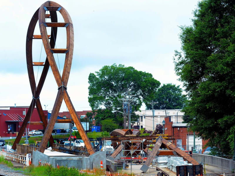
One additional point: for the base plate in photo 4, I question having two of the hold-down bolts located so far away from the location of the landing of the wood beam. Works OK for lateral, but pull-out???


spsalso
 
Kupla more:

I do see that the reason for this report was so that the PE could "...express my opinions, to-date, about the catastrophic failure...". So perhaps the thing about the design quality of the baseplates was not an opinion he wanted to express. Fair enough, I guess. I do suspect that the design of the baseplate is not the primary reason for failure, so perhaps it can be left out.

I AM interested, however, with what the design of the baseplate illustrates as to quality of design and installation.

It struck me, when I read that this installation cost $750,000, that that number seemed low (not that I have experience in judging). If it IS low, that could account for a certain style of approach to the task.


spsalso
 

I do a lot of stuff that is unusual... I thrive on it. I take great care in understanding the system to start with, and try to keep up with materials. Although not common, there was nothing distinctly different from a normal structure. Something was likely overlooked and not taken care of. I suspect it was the geometry... but don't know for sure.


The cable and geometry may have contributed. The effect of the cable may not have been as good as inticipated.

It would be neat to see actual detailed drawings of the arch and connections.

Rather than think climate change and the corona virus as science, think of it as the wrath of God. Do you feel any better?

-Dik
 
The breaking strength of 7/8" steel cable is 31.1 tons.

The 1:5 vector ratio means that 6.2 tons of sideways force at the top anchor would break it:

12,400 pounds.

Subtract from that the "pre-tensioning" done by tightening those turnbuckles at the bottom. I wonder what that "pre-tensioning" figure was supposed to be and how it was achieved.


Once one cable is caused to snap, presumably by wind load, then the "pre-tensioning" load on the other side will add into the wind load that just caused the other side to snap.


Doesn't sound good!


spsalso
 
Status
Not open for further replies.
Back
Top