TRAK.Structural
Structural
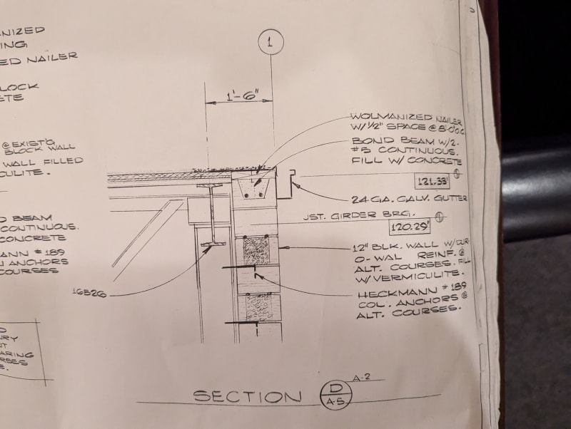
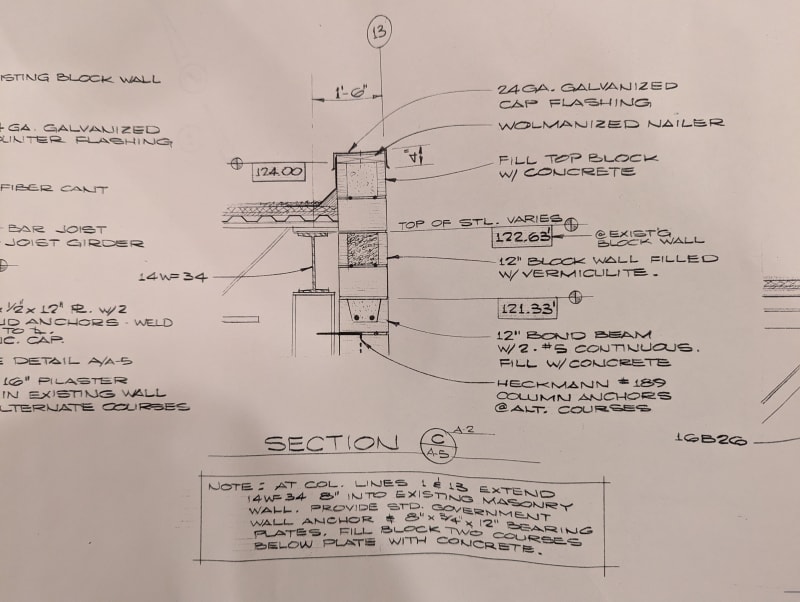
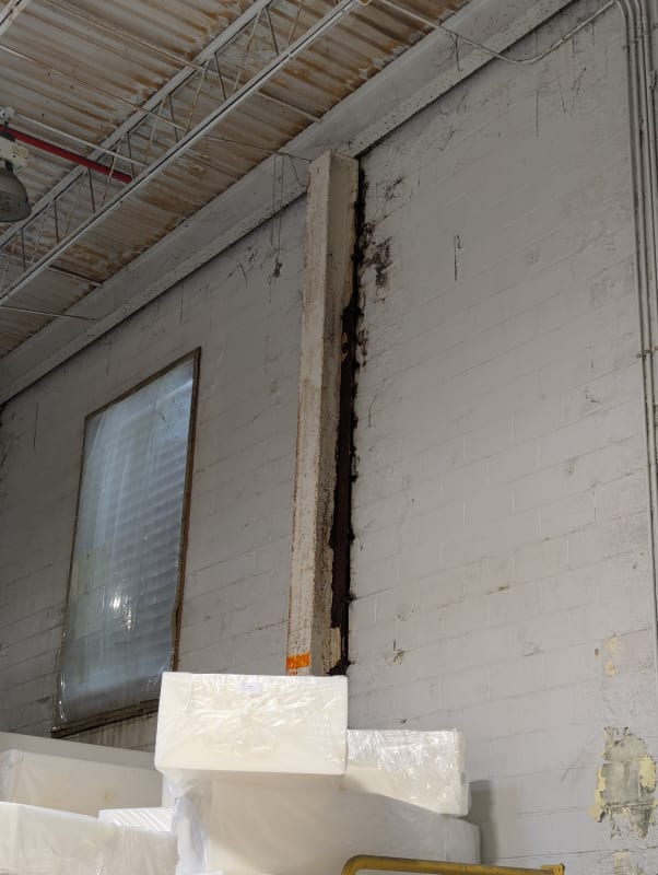
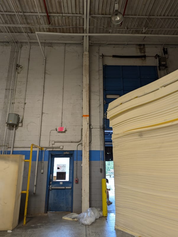
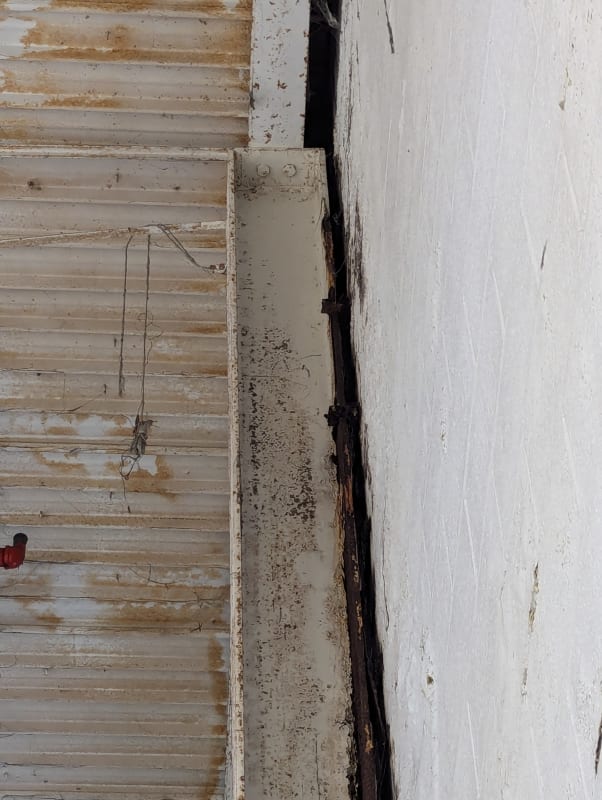
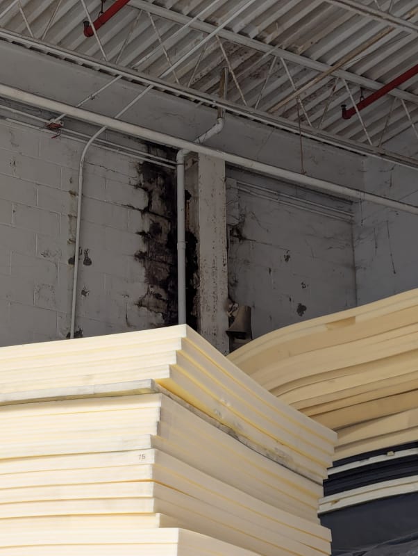
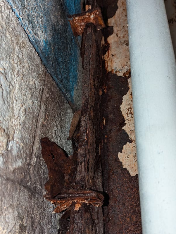
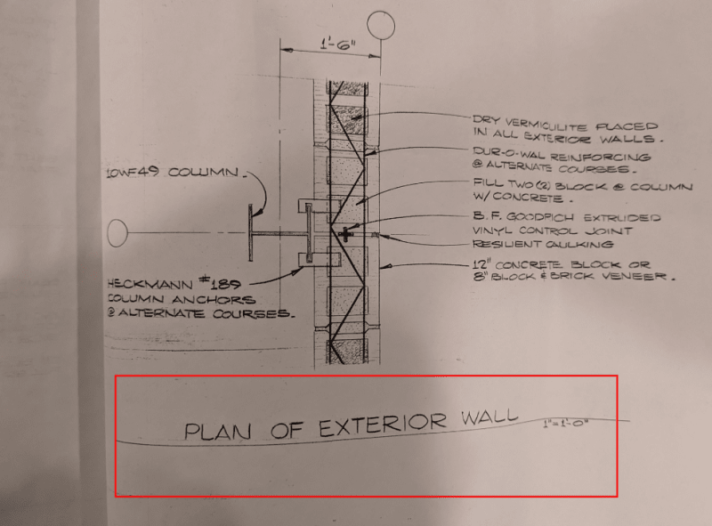
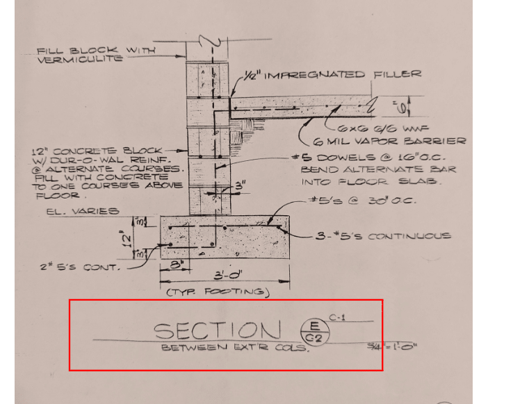
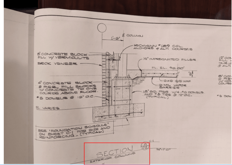
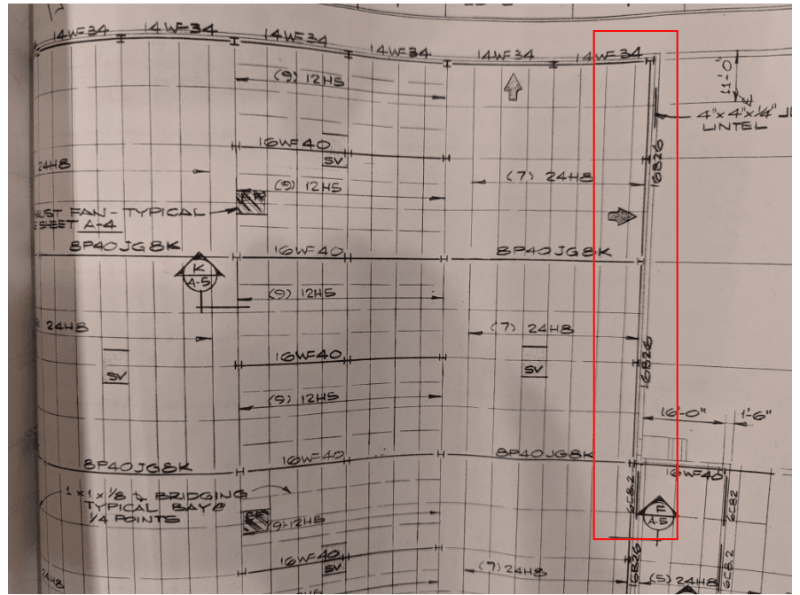
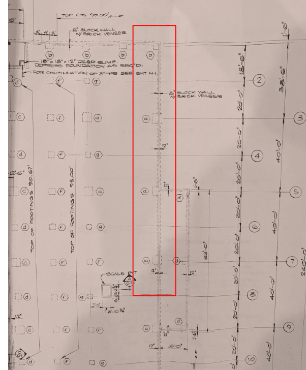
I recently got called out to look at some corrosion on some steel columns in an industrial building constructed in the 70's. General structural system of the building is steel framed with w-shape cols and roof joists/joist girders with w-shape spandrel beams. Exterior walls are CMU and appear to be non load bearing. Its only 1-story and FFE to roof is about 24 feet. Column spacing in the area of interest is 20 feet. Review of the plans has a few curious things I'm trying to understand as it may dictate some of my recommendations for repair of the corroded steel. See below screenshots. The foundation plan only shows enlarged spread footings under every other column at the perimeter. Wall sections at the perimeter away from columns do show a continuous footing. To go along with that, the roof framing plan shows the spandrel beams going over the top of the columns that have no enlarged foundation noted, and framing into the columns that do have foundations noted (this framing configuration was visually verified). Additionally there are anchors embedded in the CMU wall that connect to the steel columns at a regular vertical spacing (on all columns). And finally, X-bracing (threaded rods) is sprinkled throughout the perimeter and includes columns with and without enlarged foundations noted.
1. Are the columns with no enlarged foundations just for wind bracing of the exterior walls (and some relatively insignificant vertical loads from the spandrel beam)? Presumably these are founded on the continuous wall footing at the perimeter as the visual assessment showed that the base of all columns is below the slab on grade elevation.
2. If the answer to question 1 above is yes than the CMU would have to be horizontally spanning (or at least 2-way spanning). Was that a common way to do it back then?
3. If the answer to question 1 above is yes than it would seem the loads from the X-bracing must be small in order to justify not having discrete enlarged footings at some braced bay columns?


