Eng-Tips is the largest engineering community on the Internet

Intelligent Work Forums for Engineering Professionals

  • Congratulations waross on being selected by the Tek-Tips community for having the most helpful posts in the forums last week. Way to Go!

Air vent on closed hot water loops

Status
Not open for further replies.

rusty_sim

Chemical
Jun 12, 2017
13
0
0
VN
Hi

I have searched the forum but couldn't find a question quite like mine. If this has been discussed before my apologies

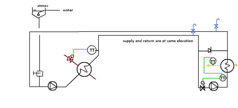
The closed loop consists of a tubular heat exchanger (for heating the hot water) and a plate heat exchanger (for exchanging heat to another fluid). The heat exchangers are in different locations so piping has to go up into a pipe rack and back down, and vice versa.

For a closed water loop like below, do I require both air vent valves or would 1 valve be sufficient?
Untitled_1_copy_copy_j1erpr.png


Now suppose the loop has a header tank for top up and thermal relief, does this change the answer to the above?
Untitled_1_copy_ghsp8r.png


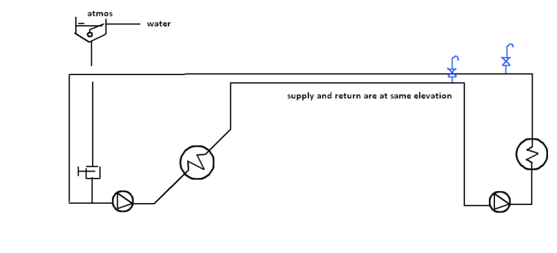
Automatic air vent valves are a bit expensive so would probably just put a 1/2" manual valve, which can be operated periodically

Kind regards
 
Replies continue below

Recommended for you

All hight points need air vent to release air that would collect at all high points. All low points need drain valve to remove dirt that would collect at low points. The thermal relief valve in figure 2 is not needed. The water level in the tank with float valve will maintain the pressure. The closed loop of figure 1 need expansion tank and makeup line with pressure regulating valve and safety relief valve to prevent overpressure if the pressure regulating valve controlling the makeup fails.
 
Hi Lilliput1

Thank you for your reply,

Apologies as I should have been more clear, I'm aware that the header tanks acts both as a top up and relief (since it is vented). And yes the closed loop would have an expansion vessel, thermal relief and pressure reducing valve. I just didn't want to sketch out an entire P&ID.

The question is do I need both blue valves? Or would 1 be sufficient ie. can the air be pushed back around?
 
If you're uncertain, why not install both?

IMO 2 high points = 2 vents. My first thought would be they are just 1/2" vents so what reasons are there for not installing them? Another thought would be for the potential of the high points being isolated from each other during maintenance or some other unexpected event. Others may disagree with me but I find it a very simple solution to just install both and save yourself the uncertainty down the road. 1/2" vents won't have very much impact on costs.

I would also suggest bumping up to 3/4" vents to allow a little more structural strength and cross section. We have a standard here which is based off the PIP PNC00005 "Design of ASME B31.3 Metallic Piping Systems" that states all vents, drains, and sample outlet connections shall be 3/4" minimum.
 
Agree it seems a little odd to be nickel and diming this for the sake of a 1/2" valve but in answer to the questions,

If your liquid velocity is more than 1m/sec / 3.5 ft/sec then you should be able to push air in front of the fluid. How you manage to push it through the second pump without wrecking the pump I don't know, but maybe it would survive a minute or two dry running.

The first pump though may trip because it doesn't have enough of a resistance or maybe it would be OK - no data

The header tank makes no difference.

We have no idea of the size and scale of this system so it's difficult to make further judgments here.

Remember - More details = better answers
Also: If you get a response it's polite to respond to it.
 
You likely have discharge check valves on the pumps, getting air to move from downstream of the second HX to a vent upstream of the second pump with a discharge check on the second pump would always cause difficulties. You need both.

[bold]David Simpson, PE[/bold]
MuleShoe Engineering

In questions of science, the authority of a thousand is not worth the humble reasoning of a single individual. Galileo Galilei, Italian Physicist
 
Hi gents

Thank you for you replies

Please see below for a more detailed sketch. The plate heat exchanger has an attemporation loop since it's for a pasteuriser, where strict temp control is required.

Untitled_1001_o37l24.png


I have snipped a 3d of the piping below. We're talking 51-101 mm (2-4") dairy tube so not large sizes and fairly short runs maybe 25 metres each way. You can see the high points near the centre of the picture as the pipes change piperacks.

2017-10-11_9-06-37_kdpuls.png


Furthermore consider another scenario: tank jacket cooling (or heating). Fluid is supplied at the bottom of the strake and returns higher up of each tank. But both supply and return headers feed off the bottom of even bigger headers. Are vents required at all 3 locations below or maybe only on the individual return from each tank?

Untitled_2_jackets_phcga7.png


Lines are typically sized for 1-3 m/s. I'm willing to put in as many required but as the p&ids are signed off, these are at my cost. Another engineer ordered the pumps, I asked him to spec non overloading motors for the DOLs but I suspect he hasn't. Although not a great solution, backpressure can be added with an orifice plate.

Kind regards
 
Status
Not open for further replies.
Back
Top