Continue to Site

Eng-Tips is the largest engineering community on the Internet

Intelligent Work Forums for Engineering Professionals

  • Congratulations KootK on being selected by the Eng-Tips community for having the most helpful posts in the forums last week. Way to Go!

Airfoil near ground "ground effect" distance (surface vehicle application)

Status
Not open for further replies.

LibertyMKiii

Automotive
Jun 26, 2019
6
Hello all,

I believe this topic is best suited in this aerospace region of the forum although it relates closely to Automotive.
Does anyone have good details on distances from the ground in relation to drag and ground effect of an airfoil?

I wanted to build a wind tunnel in the garage this summer but found the rolling road too costly to build capable of over 120 mph. (required to remove the boundary layer)

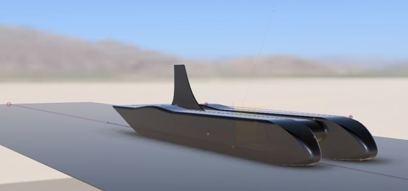
My project looks most like an salt flats land speed vehicle. The idea was borrowed from college solar cars due to the extreme reduction in drag forces while utilizing ground effect to generate the downforce needed to keep this vehicle planted at high speeds. The basic concept is "pontoons" with an airfoil suspended between them.
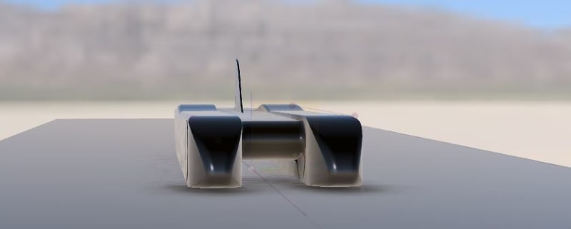
front_v1.2_a2oydv.jpg


I was able to find this graphic however it is not very specific on what the numbers are.
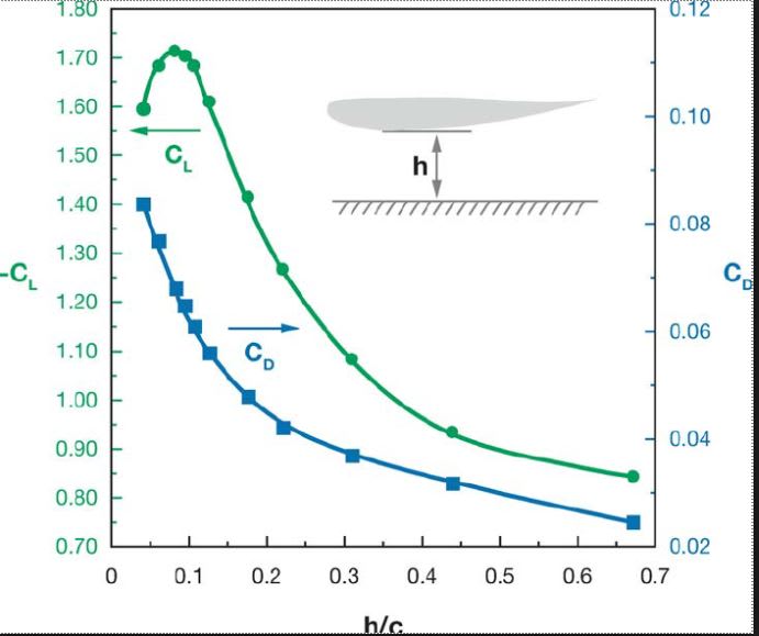
distance_sghoew.jpg


I appreciate any insights you can provide!

-Liberty
 
Replies continue below

Recommended for you

One way to avoid needing a rolling road is to mirror the item being tested so that all air deflection is symmetric and appears the same as if there is a road. This is an old technique. The mirror only needs to match to the precision required.
 
I 'assume' You already have a copy of "Aerodynamics of Race Cars: Designing for Speed"...

Also, check-out...
Regards, Wil Taylor

o Trust - But Verify!
o We believe to be true what we prefer to be true. [Unknown]
o For those who believe, no proof is required; for those who cannot believe, no proof is possible. [variation,Stuart Chase]
o Unfortunately, in science what You 'believe' is irrelevant. ["Orion", Homebuiltairplanes.com forum]
 
@3DDave I was not aware of that concept. I will remember that should I re-visit the wind tunnel dream.

@WKTaylor thanks for the link. I believe the link you provided might get me headed in the correct direction. This one specifically has very relevant data for me:
"2008-12-02
Racecar Front Wing Aerodynamics 2008-01-2988

A numerical study of a racecar front wing is presented. The focus of the study is to investigate the aerodynamics characteristics of a wing operating in a small ground clearance. A finite-span wing with a symmetric airfoil section is used. It was found that as the wing gets closer to the ground it generates more downforce and more drag. As the wing gets very close to the ground, the downforce reaches a maximum value and after that the wing generated less downforce as it gets closer to the ground. The drag force follows a similar trend of dependency on the ground clearance. The lower surface of the wing and the ground form a convergent-divergent-nozzle shape that is responsible of all the changes in the generated forces. For very small ground clearances, the boundary layers developed on the wing lower surface and the ground get closer to each other, decrease the airflow below the wing and ultimately decrease the generated downforce significantly. The study was preformed using the CFD package STAR CCM+, developed by CD Adapco."
 
I doubt you'll find an article directly applicable to your design (since everyone's design is different !)

on your chart "c" is the chord (width) of the airfoil.

But a huge impact for your design is going to be the very large "end-plates" at both ends of your "wing".

It seems odd to me that drag increases as the gap gets smaller (or as the wing gets wider); though I can see some optimum height.

another day in paradise, or is paradise one day closer ?
 
I was under the impression it was the airfoil chord length. That does change the perspective of the results for me if that is the case.
Regarding the drag forces I believe it is in relation to the distance between the airfoil/wing and the ground causing additional drag. At some point "squishing" air into a smaller space creates some significant resistance.
 
LMKii...

One element to consider for high speed vehicle drag is 'wetted area' and tapering or forward/aft blunt bodies.

The long-distance image of this vehicle implies a lot of wetted area and severe-bluntness/square-ness to the "wheel pontoons'.

Tapering and slenderness is 'twicky' art/science.

Regards, Wil Taylor

o Trust - But Verify!
o We believe to be true what we prefer to be true. [Unknown]
o For those who believe, no proof is required; for those who cannot believe, no proof is possible. [variation,Stuart Chase]
o Unfortunately, in science what You 'believe' is irrelevant. ["Orion", Homebuiltairplanes.com forum]
 
I have read about the front shape taper being a tricky thing to get correctly. The general idea/take-away I got was that a more rounded shape is safe. Setting up a sharp leading edge incorrectly could be dangerous from what I understood.

This is a better angle/view to see the shape. I am open to suggestions!

v1.2_new_tail_pzgvrs.jpg


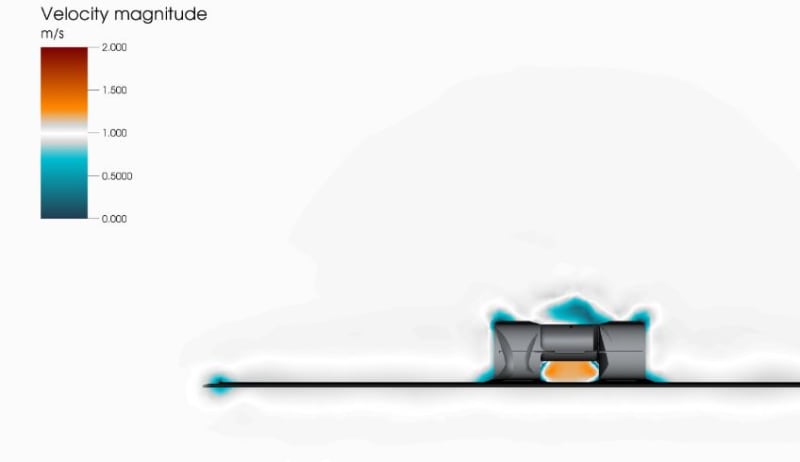
I used a free online CFD analysis, but it does not have a rolling road or specs on downforce/drag so in my eyes all I got from it was some pretty graphics with blue lines ;)
One of my largest concerns is if the downforce is balanced. If I have too much in the rear and very little in the front that could be REALLY bad!

V1.2_cfd_side_final_gr9pfo.jpg


v1.2_cfd_oo8fsb.jpg
 
damn that's a lot of wetted area, may well be the "cost of doing business", with all the shapes involved.

if the flow under the body is creating drag, would it help to have vents/ducts to the outside ? possibly NACA inlets on the outside ducting air into the low pressure under the body ?

another day in paradise, or is paradise one day closer ?
 
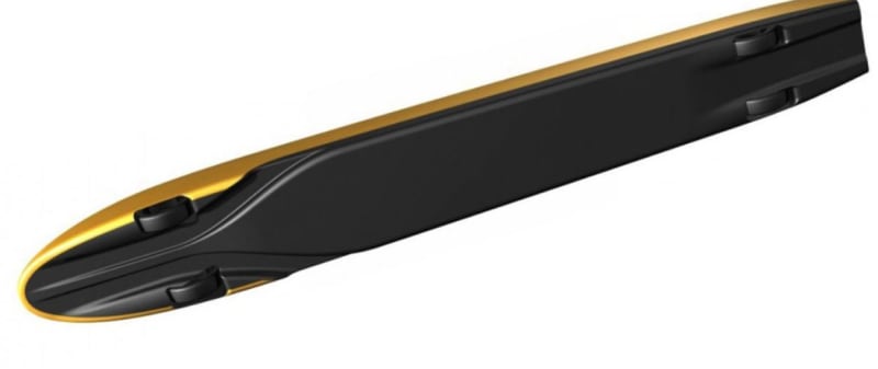
@rb1957 IF that ends up being the case I may have a v2 design later to try venting out similar to what JCB Diesel did on their land speed vehicle.
If the design creates too much drag with the suspended airfoil design then I would simply build the car like everyone else has where there is a minimal air gap under the car.

jcb_diesel_oki0ew.jpg
 
[Disclaimer: I am not an aerodynamics guy]

In such a design does one need to worry about the pitch moment created by the airfoil? I could see it being a much bigger problem with such a massive single lifting surface vs multiple smaller wings attached at different points to the car like a typical open wheel car.
 
Yes, pitch moment is important even for road cars. For high speed handling I have a limit for how much the axle lift or downforce can change.

Cheers

Greg Locock


New here? Try reading these, they might help FAQ731-376
 
@EnginerdNate
This was the reason I wanted to build a wind tunnel to determine the distribution of forces on front and rear axles.
Sadly setting up a function to simulate the traveling 100+mph boundary layer on the ground (moving belt or a complex air blowing system) was out of the budget.

-Liberty
 
Status
Not open for further replies.

Part and Inventory Search

Sponsor