Eng-Tips is the largest engineering community on the Internet

Intelligent Work Forums for Engineering Professionals

Aligning center of hole with center of triangluar feature 1

Status
Not open for further replies.

natepiercy

Mechanical
Mar 15, 2016
53
0
0
US
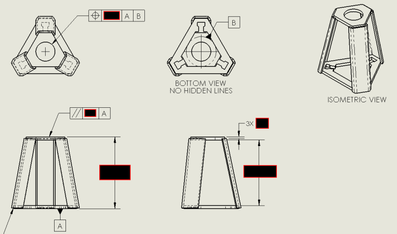
I'm very much a beginner with GD&T. My intention here is to say that the top plate must be parallel to the bottom plate (to a certain extent) and the center of the hole i the top plate must be aligned with the center of the triangle in the base plate when set on the base plate. My current struggle is that I can't find a good example of how to properly annotate the center of that equilateral triangle. Based on what I've read, a datum axis is always the product of a measurable ID or OD, so I sketched an inscribed circle in the triangle cutout on the bottom plate and put a datum target on it. Then I put a true position GTOL on the hole in the top plate, which (if I understand this correctly) says "when you set this part on datum A, the center of this feature needs to be within [dim] of datum B (the theoretical center of the triangle)". I'm looking for either affirmation that this makes sense in terms of inspection, or a suggestion for how this result should be achieved using a different method. Bonus points for references to ASME Y14.5 2009.

center_of_triangle_position_n6mprq.png


Thanks in advance.
 
Replies continue below

Recommended for you

You did it perfectly well.

Your "inscribed circle" creates what's known as "irregular feature of size" and suitable for being a datum.

Now, think haw would you gauge your part (or how it will interact with the mating parts).

If you find it necessary to simulate your mating parts with expanding devices (chick, collet), than you can leave your position control at RFS (nothing specified in frames).

If your assembly conditions may be simulated with simple solid pins, then you may benefit from using MMB/MMC synbols.

"For every expert there is an equal and opposite expert"
Arthur C. Clarke Profiles of the future

 
Drawoh,
Yes, this is a weldment. As far as accuracy, the parts are currently coming in from China, and their lack of parallelism and alignment is visible (even to the untrained eye) in 5% or more of parts. My goal is to establish some criteria for inspection that gives our customer a) the ability to request exactly what they want, and b) a grounds to reject parts that aren't acceptable. These GTOLs won't be harsh, by any means.

CheckerHater,
Thank you. If I really think about this, the critical features that would define my "irregular feature of size" are the three cutouts at the point of the triangle. If I were making this as closely tied to design intent as possible, I suppose I would need to define the midpoints of the furthest lines as the three points that define my feature. However, because of how difficult that would be to gauge (compared to a simple 1-piece turned pin) and because I know this is going to be laser-cut, I'm taking the leap of faith that there shouldn't be any difference in result between the two ways of defining that datum. The true position tolerance is an excellent candidate for an MMC tag. I don't know why I didn't think of that! Thanks for the suggestion.
 
You could do this by datuming the 3 faces and splitting the datum evenly. ie: measure the distance from the small face to the longer face 3 times. Put the datum of each on the end of the lengths showing the centreline of each.
positional tolerance would be:- A/B-C-D assuming A is the face you are drilling into. The other datum priority is split evenly giving you the centre of all 3 features.
I would prefer to put datums on proper measurable features rather than centrelines etc.

 
Status
Not open for further replies.
Back
Top