Eng-Tips is the largest engineering community on the Internet

Intelligent Work Forums for Engineering Professionals

An unusual feature (to me) on a steel truss bridge 1

Status
Not open for further replies.

spsalso

Electrical
Jun 27, 2021
942
0
0
US
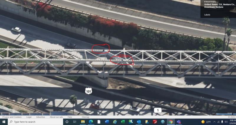
Below is a link to a photo of a railroad bridge (build date 1961) over Highway 101 in Ventura CA:


I see that as being a two-span truss bridge.

I am wondering about the reason for the horizontal member along the top, immediately over the center pier. I believe usually this is empty space, in such a structure.

As in this delightful old bridge:


Can someone explain?


spsalso
 
Replies continue below

Recommended for you

"Here's one for you: this is an old bridge with a relatively complicated design when compared to typical railroad truss bridges."

No, it's a two span through truss bridge. You think THAT'S a complicated design? Please explain why you think this.


"We're trying to interpret the load paths from some cobbled together google images and images of bridge 'enthusiasts' that have been collected."

Nope. Only one "enthusiast" here. I have no co-conspirators. Perhaps YOU can explain the load paths for members that have one end not connected to the structure. And rivets that don't rivet.

I am puzzled by your use of the term "cobbled together". Do you somehow think I built these images from scraps or something? They are there for the looking. And seeing.

"Why does it matter?"

It matters because some people who are interested in bridges like to know how they work (perhaps this idea is foreign to you). I asked my original question to that end. Thanks to the responses in this topic, I was inspired to keep examining this bridge until I had an answer.

It is unfortunate that you intended the term 'enthusiasts' as a pejorative (the quotation marks give it away). Perhaps you don't like people outside your professional field having an interest in it. For myself, I always welcome people from outside my field asking questions and showing an interest.


spsalso


I will mention that I do not have a negative opinion of anyone involved in the construction of the subject bridge.

As an 'enthusiast', it is one of my favorite bridges. Every time I travel on 101 down to LA or back, I always look forward to seeing it.

I am now quite convinced that there was input to the design from people not at all interested or knowledgeable in bridge design. And I also believe that the engineers who dealt with this input did a pretty good job of it.

I would VERY much like to know the details of the above. I bet it would make a great book. For those who read.


spsalso
 
The latest of the two links is 2011; things may have changed. This might be the link where I found it is owned by the county but the local ownership link is down.

Link

I was looking at the bridge in Bing bird's eye view; the dark area seem to suggest the top chords at one end are only connected to the outside gusset plates. Another observation that hasn't come up: At the pin and the edge of the pin plate there's no sign of paint wear. I discussed this with a colleague, he agrees that we need plans to understand the function of these members. He also believes that the vertical is connected to two gussets at the bottom.

Inked1_LI_cimadf.jpg
 
That's a very nice picture. For the area circled by the upper red, you can see the diagonal line of the exposed edge of the end post. And, obviously, the lack of top gussets at either location, unlike the rest of the bridge.

The paint wear point is interesting. If there is no sign of paint wear, I guess that would mean the joint did not move enough to cause it.

Did your colleague see the photo example above that included the red line? I note that only three rivets would make the connection between the vertical and the right-hand gusset. Did he have an opinion of why there were only three on the right while there were 16 making the same type of connection on the left? Surely a curious case of asymmetry.

And I still have a problem with those three either missing the flange on the vertical or being very near the edge of the flange.


spsalso
 
Maybe architectural/aesthetics???

A proper looking road improves safety: diagonals, skews, angles and gaps make the roadway look confusing.

The infill will provide some continuity of the superstructure, which will improve seismic response, but my bet is that it was primarily done for the perception of the highway drivers.

The bridge looks weird to the driver traveling toward and under the bridge--and would look more bazaar without the infill. The bridge is heavily skewed to the highway. And the bridge is also heavily skewed to its pier supports. Skewed skewed skewed. The connection is for Bridge Aesthetics (for the drivers on the road), it attempts to look like a continuous box-girder.

The CA Division of Highways was not building many truss bridges by the 1960's. I've driven under that bridge thousands of times and have stayed in the Hotel "The Vagabond" right next to the truss-bridge several times.


I have real doubts that the impetus to add the "decorative structure" came from highway designers. This was 1961, and I do not believe such thoughts entered the minds of California highway and bridge designers.

I see it more as coming from some hissy-fit local politician who thought it looked stupid having a notch in the middle, and had enough pull to get his way. I will even concede that he could have been visually correct. But not structurally.

Again, I think there's a book in this. I'd be tempted, if I lived there.


spsalso
 
I don't want to disillusion you, but, I don't think this bridge is worthy of a book. Besides, it wouldn't be much of a book as there's nothing extraordinary about the bridge.
 
Oh, it's not so much the bridge that's the subject, but the people.

Not that the former wouldn't be of some interest. Once the designers were instructed to add the decoration, they had to both design it and work it into the installation. I'm curious what options they went through. Since they most likely were used to only doing "real" structures, this was, in a way, new to them.

For example, why did they choose to pin one end of "the floppy piece", and use a landing at the other? Why didn't they make two pockets at each end and just drop the piece in? Are the pieces made from steel just as thick as the load bearing pieces?

Ah, but the people: I assume that originally it was designed as a simple two-span through truss bridge. And someone, almost surely not an engineer, said that it was ugly and stupid and needed that big gap filled up, in the middle. The designers said: "No it doesn't. That's silly." And it just grew from there.

Wasn't there a movie called "Chinatown"? Wasn't it about some boring old ditches that people dug, and the people who had input to that project?

spsalso
 
So then would the pins be a loose fit for those dummy members, so that they wouldn't accidentally take a load?

I've just read that they add dummy members to cantilever steel bridges so that they don't scare the public into thinking there's missing pieces.


spsalso
 
In the detail shown, the pin is in a slotted hole and sits on a bronze angle so that the top chord can expand/contract.

Depending on the contractor's erection method, the dummy member could carry load if the center span is constructed by cantilevering all of the members. Once the closure is made it becomes a dummy. If the contractor elects to raise the suspended portion of the center span into place, then the dummy is always a dummy.
 
I'm pretty sure the bridge was built all at once in 1961.

Unfortunately, the rather large amount of on-line time I spent trying to find out about the construction of this bridge revealed no original sources.


spsalso
 
The 1st photo shows a 2-span continuous truss bridge.
The 2nd photo shows a 2 simply-supported truss bridge.

The span of continuous bridge generally is larger than simply-supported truss bridge.
For shor span bridge, simply-supported bridge is easy to built and costs less.
 
netsonicyxf,

"The 1st photo shows a 2-span continuous truss bridge."

And how are loads transmitted through the top member that is directly above the center pier, considering it is not attached at its western end?

How do you explain the radical asymmetry of the rivet patterns in the gussets in the area above the pier?

And, for extra points, you can explain the reasoning of having 4 bridge shoes on the pier, instead of two. How does the loading work through those four points, under a continuous truss bridge?


spsalso
 
Status
Not open for further replies.
Back
Top