Continue to Site

Eng-Tips is the largest engineering community on the Internet

Intelligent Work Forums for Engineering Professionals

  • Congratulations cowski on being selected by the Eng-Tips community for having the most helpful posts in the forums last week. Way to Go!

Analysis of Statically Indeterminate, yet very simple, Bracket 10

Status
Not open for further replies.

nargonaut7

Mechanical
Dec 1, 2021
20
Greetings everybody,

I am sorry that my question has already been presented in this forum, but the previous answers, at least those two that I have been able to find here, are not adequate, as I explain later.

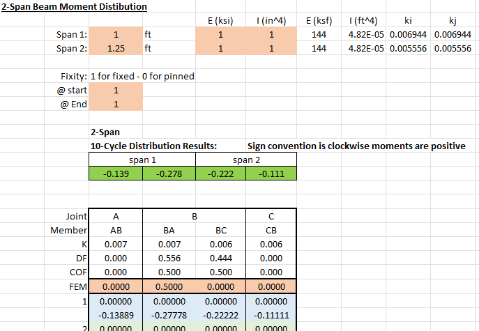
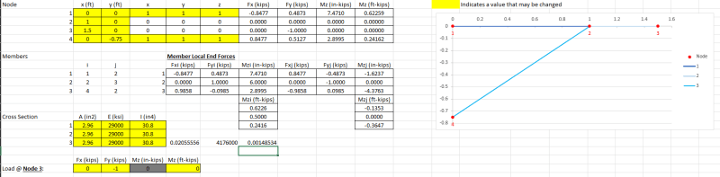
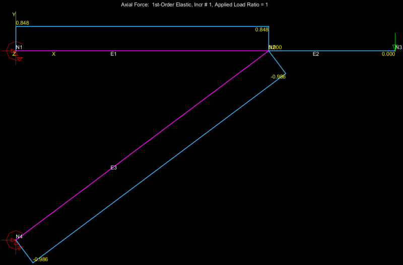
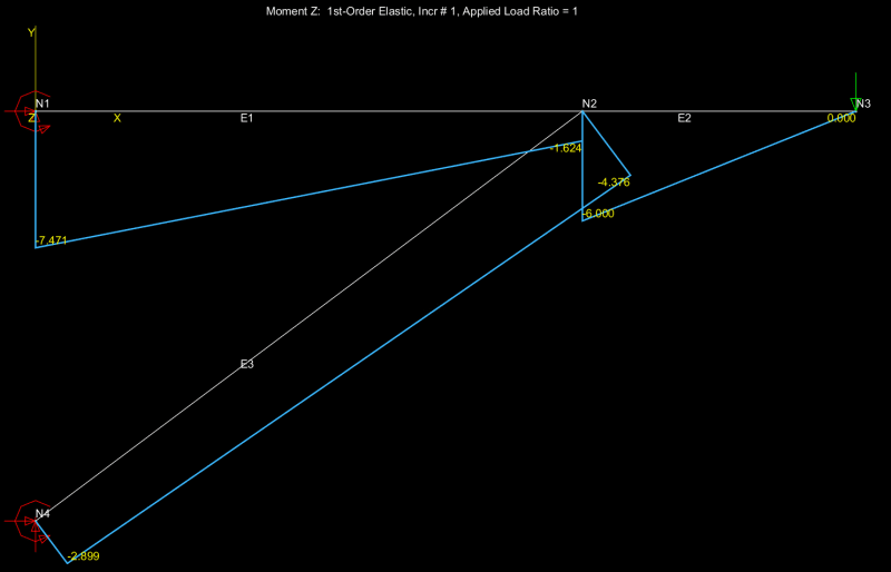
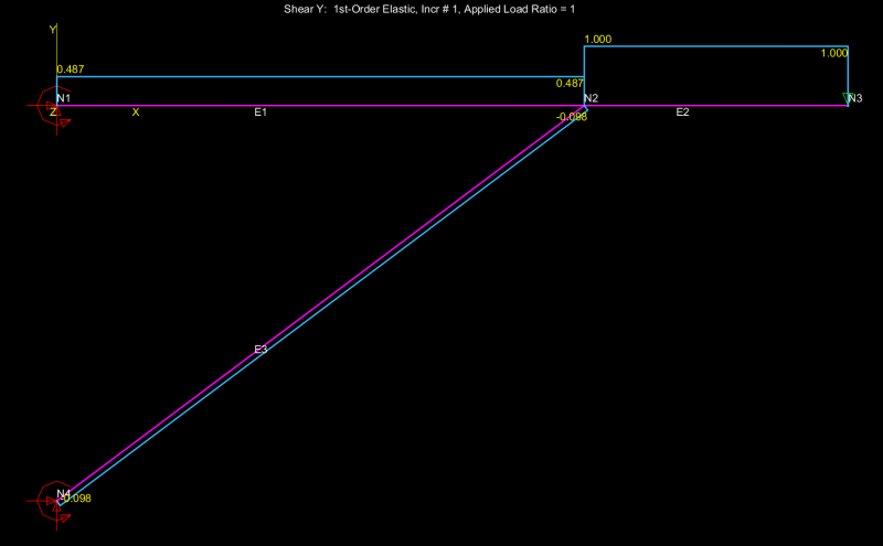
My situation, as shown below, is that of the second-simplest possible structure: a two member-frame attached to a wall (this is the second-simplest structure because the two absolute simplest structures have only one member, which is either a cantilever beam or a single-standing column, with their supporting wall or floor, respectively; by the way, I am writing all this not with the purpose of giving a lecture but only to make my point as clearly as I can). So, it really bothers me that excellent books such as Roark’s “Formulas for Stress and Strain”, “Structural Engineering Handbook” by Mahamid and others, and “Structural Engineering Formulas” by Mikhelson and Hicks, these three books include formulas for much more complicated frames, when this simple bracket support I am showing here, which is used in industrial plants all over the world, is completely ignored. Neither this two-member frame is shown as an example in multiple books where I reviewed the Three-Moment Equation, the Moment Distribution Method, Castigliano Theorem, and the Slope-Deflection Method, to verify if I could apply any of them to my situation. A severe disappointment I got was with the Slope-Deflection Method, when the determinant of the 4 x 4 matrix of the coefficients of the variables, calculated with the particular dimensions and the weight “P” of my application (none of these parameters are needed to be indicated here) turned out to be zero. Another disappointment was when I used Roark’s Tables 8.8 and 8.9, to combine axial and transversal deformations using the fact that the deformations of both members at the joint “C” are the same. By trial and error, I found multiple combinations of the three internal reactions (two forces and one moment) at that joint that make those two vertical deformations equal, so that didn’t work either.

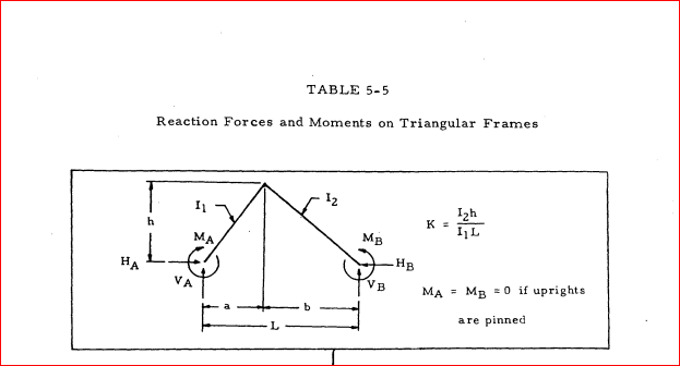
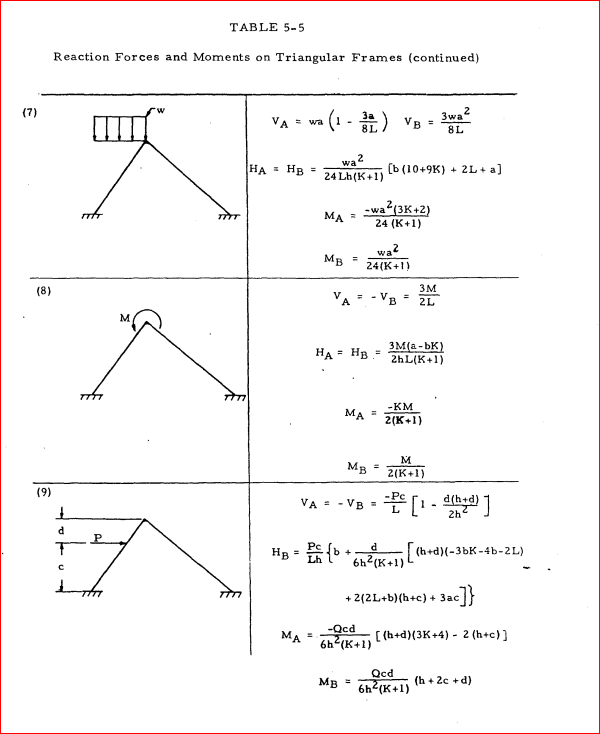
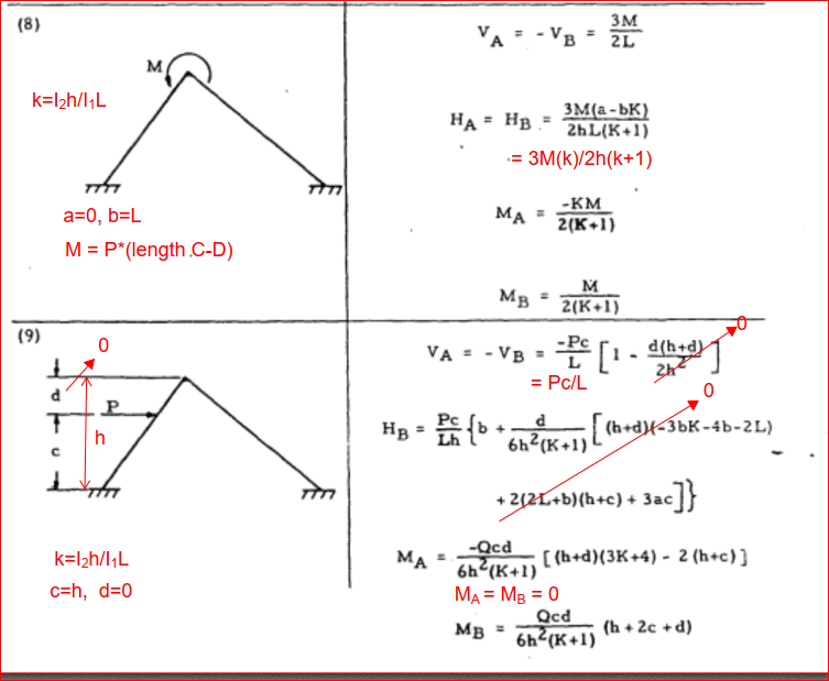
I thought I was close to calculating the reactions in this bracket, when I found the “Air Force Stress Analysis Manual”. Its 579-page PDF file can be easily downloaded for free by searching in internet with those words. The reactions and moments I calculated for a triangular frame (Table 5-5) with all three joints fixed and with an external moment applied (Case 8) satisfied all the Statics summation of forces, but this didn’t happen with an external load (Case 9), so I couldn’t combine those two cases to simulate my bracket, as was my plan. That Case 9 didn’t work even when I tried to solve the exact situation they show, which is that both members are inclined and that the load is applied between supports, not in the overhang as in my situation. So, when I couldn’t even solve the standard problem shown in the diagram of Case 9, plus my failures calculating with Roark and Slope-Deflection, as described earlier, that was when I realized that I need to ask for help. But, of course, these failures could be also because I made a numerical error.

If somebody wants to verify these formulas, or any other method, you can assume your own load, dimensions, and inertias for those two members, and check if the resulting reactions you get make all the Statics summations equal to zero.

Back to the previous answers, I have seen two of them, I want to mention this to save somebody’s time in replying. The first one is the advice to use an FEA software, which of course I will use, but I always want to see a manual calculation of forces and stresses, at least for simple cases like this bracket support, to be included in a design report together with software results. The second answer is the advice to assume all three joints as pinned. This simplification reduces the problem from statically indeterminate to determinate, and I already did that, then it becomes really simple, the maximum moment in AD is P times the distance CD, the same as if the joint “C” were a fixed support and then we only consider the overhang, I found that result surprising. This quick and simple approximation can be useful in many situations, we can always use a higher safety factor to cover us if the actual moments and stresses are higher than the calculation, but I am beyond this point, it has become a matter of honor for me to find the method or formulas to calculate all nine reactions with all three joints welded as accurately as practical. The caveat of being practical is important so, to clarify my position, the extremely long formulas of the Air Force manual and of Roark are fine with me.

Well, I will appreciate very much any help, and I hope somebody will find useful the four references I have included in this post. And sorry for writing so much.


 https://files.engineering.com/getfile.aspx?folder=fa0c64d2-7f68-45b5-afd6-a97e8bac3f02&file=Bracket.PNG
Replies continue below

Recommended for you

Thank you, centondollar, for your reply.

Sorry, I couldn't follow what you wrote about determinants and buckling. I used determinants when I tried to solve the 4 x 4 system I got by writing slope-deflection equations, a method which, as I wrote earlier, I learned only a few weeks ago (I am a mechanical engineer). Earlier I wrote which are the four unknowns I have there. But the determinant I got is zero. However, after a previous answer from BAretired in this thread, I am hopeful about this method because I understood that it is applicable, even if a few weeks ago I reviewed my equations and couldn't find my error. But certainly that sounds easier than the maxwell-mohr integrals you mentioned.

And, when you mentioned that my case is not in textbooks, I think it is surprising and disappointing that this extremely simple and common bracket is not included in the three manuals of formulas I listed in my original post. Manuals of formulas are different from textbooks. But, as I wrote before, the Air Force manual is really close, so I should have indicated before that this manual says that the formulas for frames are from "Handbook of Formulas for Stress and Strain" by William Griffel. I wonder if this book would not have the typo the AF manual has in Case 8 of Table 5-5. In my original post I included the way to download this large manual.

Finally, you gave me a lot of details about how to calculate the statically determinate version of this bracket, with all three joints pinned. As I wrote in my original post, I already solved it, and even indicated in my original post its main result.
 
Here are the Air Force images:

Capture_jwnjhb.png


Capture01_kamkbv.png


BA
 
Yeah, there's no way I would submit calcs in which I beat one of those diagrams to fit this situation. Use a frame analysis program.
 
Thank you, rb1957, for your reply.

I am going to try the iterative method you explained, it starts in a similar way to what I discussed earlier in this thread with desertfox. But I think that the iteration you described solves my concern, which I mentioned with desertfox about an excessively high force on "C".

Regarding the USAF manual, in my original post I included how to download it, but since you are in the road, here I am attaching the two cases I was planning to combine. But my plan failed because case 8 is not working not even for the configuration they show, without doing any adaptation to make it similar to my bracket (a = 0, and making d = a negative value to locate the force in the overhang), and I think it is because they have a typo with the Q they show in the MA and MB formulas. That Q has to be a force for those formulas to be dimensionally correct, but when I Plugged my "P", the reactions I got don't make the summation of moments equal to zero. I can't imagine what other force can be plugged in those formulas. As I wrote before, they say they copied those formulas from a Handbook by Griffel, but it costs $105 in Amazon.
 
 https://files.engineering.com/getfile.aspx?folder=310a37e7-e0b3-4b8b-9b03-0be138fd3146&file=AF_Frame_Formulas.png
If he submits slope-deflection manual calcs or matrix analysis outside of a commercial program, then I'd assume he's very inexperienced probably just coming out of school, and needs more supervision from his superiors.

Pay attention to this, Nargonaut. This is probably the best case scenario if you submit what you're talking about.
 
Thank you, BAretired, for your second and third replies.

And yes, those snapshots you uploaded are what I have been using, I just attached them to reply to rb1957, but I don't know how to include pictures directly in this page. Let me copy here what I wrote to rb1957 about the problem I found with Case 8. "But my plan failed because case 8 is not working not even for the configuration they show, without doing any adaptation to make it similar to my bracket (a = 0, and making d = a negative value to locate the force in the overhang), and I think it is because they have a typo with the Q they show in the MA and MB formulas. That Q has to be a force for those formulas to be dimensionally correct, but when I Plugged my "P", the reactions I got don't make the summation of moments equal to zero. I can't imagine what other force can be plugged in those formulas. As I wrote before, they say they copied those formulas from a Handbook by Griffel, but it costs $105 in Amazon."
 
Sorry about the snarky response. That didn't come across exactly how I intended.
I was giving this some more thought while out for a ride.
First off, if I'm not mistaken, typical frame analysis neglects axial deformation.
If you make that assumption here, then that junction point can't shift- it's held in position. The beams can rotate there, but not shift either direction.

So you can treat it as two cantilever beams fixed at the left side, each with one unknown lateral force at the junction. And one unknown moment at the junction.
From Roark's Formulas for Stress and Strain, you can find equations for the displacement at the junction point of each beam, and set those displacements equal to zero.
And you can find equations for the rotation at that point on each beam and set rotation on beam 1 equal to rotation on beam 2.
That leaves you with three equations and three unknowns.
Assuming that works out, you can sum vertical forces at the junction to find the longitudinal force in the lower beam.
And sum horizontal forces at the junction to find the longitudinal force in the upper beam.

It's not uncommon to have situations like this where using some nominal size of member gives a capacity of ten times what you need, which is one reason for the approximate methods.
You may get out-of-plane erection loading that would be hard to predict.
For one-off designs, it may be worthwhile to change the actual geometry to match the analysis rather than the other way around.
On the support surface at left, if that's concrete, you probably will have some sort of base plate in there, and it would make more sense to use the pinned joint assumption. If that surface is thin steel with a welded connection, it would likely not have adequate rigidity for a fixed connection, and the pinned assumption would still work.
The AISC code has provisions for buckling of flat bars loaded in plane that may help.
 
Thank you, 271828, for your second reply, and also thanks to steveh49, this reply also answers his post

But I don't agree with what you wrote "This bracket is not a typical configuration for which I would expect to find closed-form solutions in a handbook" because, as I have written before, three handbooks (Roark, Hicks, and Mahamid) have closed formulas for brackets with three and more members, and with all-fixed joints.

Now, regarding the other part you wrote "submits slope-deflection manual calcs or matrix analysis outside of a commercial program", as I said in my original post, which I know was very long, I will do an FEA analysis using a well-known software, this is just a manual verification I want to include in the design report. I think that submitting only software print-outs, without showing due diligence with formulas, for simple cases like this one, doesn't look good.
 
Verifying analysis doesn't necessarily (or often) mean reproducing the exact same answer by hand. If you have FEA results, appeoximate checks that bound the answer (eg the pinned assuption, and a propped cantilever analysis) may even be better. If the check calc is too complex, you run greater risk of an error in the check as well as the FEM analysis.
 
Here's my suggestion: Use the software and verify by hand with the simplified model treating the connections as pins and the end of the brace to be a hinge. If this gives you a result very close to the software output, then you can just use the hand method in the future. If it gives you results that are kind of close, then you can determine whether they are reasonable (eg the tip deflection is 15% less considering everything fixed than by using the pinned hand method). If either the software results don't make sense (eg there is more tip deflection than the hand method even though it should be stiffer), or they are very far from the hand method (eg the tip deflection is 10 times higher using the hand method), then you can keep investigating.
 
"Sorry, I couldn't follow what you wrote about determinants and buckling. I used determinants when I tried to solve the 4 x 4 system I got by writing slope-deflection equations, "

Then it is no wonder that the result did not make sense. I reiterate: determinants are not used to solve the linear system of equations that results from writing the slope-deflection equations. The condition "determinant vanishes" is related to eigenvalue buckling analyses (zero determinant means that the coefficient matrix is non-invertible, i.e., that there is not a unique solution but rather many possible buckling mode shapes and multipliers), which can also be done using modified slope-deflection formulas (Berry´s formulas), but that is not an analysis that gives moments, shear forces and normal forces.

Regarding "showing due diligence", the due diligence can be done in a straightforward manner: use the finite element method with simple elements (e.g., beams) and simple idealized boundary conditions, which will result in the same value as a hand-calculation. Finite element software is not magic - for frames with beams, it merely employs a slightly more elegant type of slope-deflection method to solve the problem.
 
Thank you, JStephen, for your second reply, and no problem about your previous reply, sometimes we can't resist making a joke, but most good jokes are sarcastic or politically incorrect. Maybe I also over-reacted.

You pointed that many methods don't consider axial deformation, a point that was also indicated earlier by BAretired, and I forgot to acknowledge it, it has been hard to keep up with so many replies. Actually, I am going to call it a day after this reply, it is late in the East Coast of the US, maybe there are some replies from overseas. But yes, I have no problem with the simplification of neglecting axial deformations, I want to show some calculation that is more advanced than simply all-pinned, but at the same time the design report is not the place for a dissertation in solid mechanics.

Now, I applied Roark Tables 8.8 and 8.9, and those formulas indeed consider axial deformations, and I also had three unknowns, but reactions, not displacements, and got multiple sets of reactions that would satisfy the Roark equations, so I didn't spend time checking them with the Statics summations, because I thought that this approach was not valid. So, next week (tomorrow I will have to work in another project) I would need to review your approach.

To answer your other questions, this bracket will be used in many locations, with different loads, dimensions, and sections, but I can't know the exact number. So, I am hoping to learn a method to calculate the reactions, or even better a set of formulas, like those of the AF Manual, that can be used to calculate multiple configurations, even future ones that may come up. And, the wall where these two steel members are welded will always be large steel columns, which could be safely assumed as extremely rigid. Returning to the AF Manual, if somebody would have the Griffel book referred there, maybe it would solve the "mystery" of that Q, that could be the key to solving this brackets for multiple configurations very easily, those formulas could be programmed in Excel, to simple change the input parameters. Another promising approach I got from today's replies is that of the Slope-Deflection Method, if I could find what is the mistake I made that I got the determinant equal to zero.
 
When you get moments out of the analysis, be sure to check those welds to make sure they can provide moment connections.
 
I saw your pic from the USAF manual. Is it clear that the joint in the triangular frame is fixed, like your sketch ?

I assume the triangular frame is ABC in your sketch, and you're loading it with a force and moment (simulating the load at D).

I think the first question, before analytically considering the structure is to model what the structure really is. Apologies if this has been discussed already. If the joints are welds or multiple fasteners then some fixity is to be expected. If I analyzed the joints as pinned, and a reviewer asked "why not fixed?" I'd say that the fixity moments are small, the simple analysis margins are high, and if he insists we can test the structure (either in situ or on a bench, either the production parts (if the margins are high) or a test piece. But then maybe you don't have the years (decades) of experience that a reviewer can use to appreciate the sense of my opinion. If you are new, then working through a couple of examples will convince you (and you don't need to rely on "some guy on the internet". I would solve with manuals (hand calcs) and FEA. FEA is a very useful tool, and reviewers are always asking "why should I believe your FEA ?" ... it's nice to say that you've hand solved similar structures with similar FEAs and got consistent answers.

another day in paradise, or is paradise one day closer ?
 
Air Force Solution:

Note V & H represent H & V in the OP's model. This was done in a hurry, so should be checked. I couldn't find Q, but it doesn't matter because d=0, so the whole expression is zero.

To find the final answer, use superposition, i.e. add Case 8 and Case 9 together.

Capture_hl2pph.png


BA
 
Just checking, in Roark's Formulas, 5th Edition, Table 4, "Reaction and Deflection Formulas for Rigid Frames", the member areas don't enter into the results, so presumably the table is not considering axial deformation. Similarly, I assume shear deflections are excluded.
 
nargonaut7 said:
To get the determinants of matrices, ...
why are you calculating the determinant, you need to go through the book at the link I posted it covers matrix structural analysis.

Post some of the calcs you've done so far and we may be able to help steer you in the right direction. Then I'll share a small spreadsheet built from that textbook for your sketch condition.

 
Steveh49:
EDIT: I follow what you did now, simple 1 cycle moment distribution simple because both supports are fixed and the members aren't loaded along their length, so 1/2 joint moment carries out to the fixed end. Neglect axial deformation. Split out member AC and BC on their own as fixed-pin beams with moment from the distribution applied to the end. Vertical force to the top of BC = AC right end reaction plus the 1 kip load plus the vertical component of BC right end reaction.

textbook style setup for Steveh49's first steps in getting the moments applied at each end of the members and support moments:
Capture_p5fouo.png


Matrix Analysis Method -- considering first order axial deformation:
Capture_w8c8bp.png


Verified by MASTAN2
Axial:
Capture_lrjusm.png

Mz:
Capture_r2fctp.png

Vy (local member shear):
Capture_mfjyw3.png


Node Reactions:
Capture_tzaeip.png

Capture_om0cgy.png
 
Status
Not open for further replies.

Part and Inventory Search

Sponsor