nargonaut7
Mechanical
- Dec 1, 2021
- 20
Greetings everybody,
I am sorry that my question has already been presented in this forum, but the previous answers, at least those two that I have been able to find here, are not adequate, as I explain later.
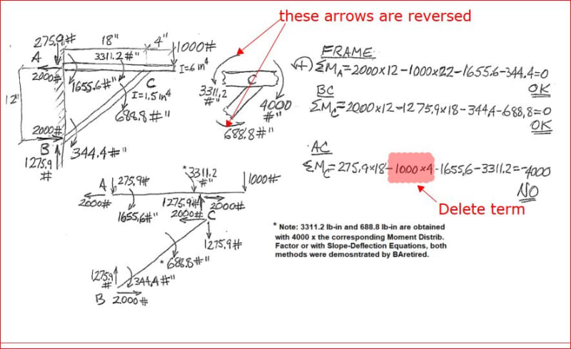
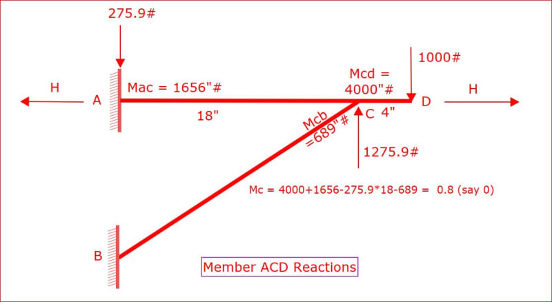
My situation, as shown below, is that of the second-simplest possible structure: a two member-frame attached to a wall (this is the second-simplest structure because the two absolute simplest structures have only one member, which is either a cantilever beam or a single-standing column, with their supporting wall or floor, respectively; by the way, I am writing all this not with the purpose of giving a lecture but only to make my point as clearly as I can). So, it really bothers me that excellent books such as Roark’s “Formulas for Stress and Strain”, “Structural Engineering Handbook” by Mahamid and others, and “Structural Engineering Formulas” by Mikhelson and Hicks, these three books include formulas for much more complicated frames, when this simple bracket support I am showing here, which is used in industrial plants all over the world, is completely ignored. Neither this two-member frame is shown as an example in multiple books where I reviewed the Three-Moment Equation, the Moment Distribution Method, Castigliano Theorem, and the Slope-Deflection Method, to verify if I could apply any of them to my situation. A severe disappointment I got was with the Slope-Deflection Method, when the determinant of the 4 x 4 matrix of the coefficients of the variables, calculated with the particular dimensions and the weight “P” of my application (none of these parameters are needed to be indicated here) turned out to be zero. Another disappointment was when I used Roark’s Tables 8.8 and 8.9, to combine axial and transversal deformations using the fact that the deformations of both members at the joint “C” are the same. By trial and error, I found multiple combinations of the three internal reactions (two forces and one moment) at that joint that make those two vertical deformations equal, so that didn’t work either.
I thought I was close to calculating the reactions in this bracket, when I found the “Air Force Stress Analysis Manual”. Its 579-page PDF file can be easily downloaded for free by searching in internet with those words. The reactions and moments I calculated for a triangular frame (Table 5-5) with all three joints fixed and with an external moment applied (Case 8) satisfied all the Statics summation of forces, but this didn’t happen with an external load (Case 9), so I couldn’t combine those two cases to simulate my bracket, as was my plan. That Case 9 didn’t work even when I tried to solve the exact situation they show, which is that both members are inclined and that the load is applied between supports, not in the overhang as in my situation. So, when I couldn’t even solve the standard problem shown in the diagram of Case 9, plus my failures calculating with Roark and Slope-Deflection, as described earlier, that was when I realized that I need to ask for help. But, of course, these failures could be also because I made a numerical error.
If somebody wants to verify these formulas, or any other method, you can assume your own load, dimensions, and inertias for those two members, and check if the resulting reactions you get make all the Statics summations equal to zero.
Back to the previous answers, I have seen two of them, I want to mention this to save somebody’s time in replying. The first one is the advice to use an FEA software, which of course I will use, but I always want to see a manual calculation of forces and stresses, at least for simple cases like this bracket support, to be included in a design report together with software results. The second answer is the advice to assume all three joints as pinned. This simplification reduces the problem from statically indeterminate to determinate, and I already did that, then it becomes really simple, the maximum moment in AD is P times the distance CD, the same as if the joint “C” were a fixed support and then we only consider the overhang, I found that result surprising. This quick and simple approximation can be useful in many situations, we can always use a higher safety factor to cover us if the actual moments and stresses are higher than the calculation, but I am beyond this point, it has become a matter of honor for me to find the method or formulas to calculate all nine reactions with all three joints welded as accurately as practical. The caveat of being practical is important so, to clarify my position, the extremely long formulas of the Air Force manual and of Roark are fine with me.
Well, I will appreciate very much any help, and I hope somebody will find useful the four references I have included in this post. And sorry for writing so much.


