Continue to Site

Eng-Tips is the largest engineering community on the Internet

Intelligent Work Forums for Engineering Professionals

  • Congratulations SDETERS on being selected by the Eng-Tips community for having the most helpful posts in the forums last week. Way to Go!

Another dream engine

Status
Not open for further replies.
Replies continue below

Recommended for you

It's an inline 4 with a yoke instead of connecting rods. If this doesn't turn out to be another pipe dream that never sees the light of day I'll be shocked.
 
Doesn't doubling the power in the example for outboard motors mean that the propellers need to scaled up? Is that a straightforward doubling of the swept area?

TTFN (ta ta for now)
I can do absolutely anything. I'm an expert! faq731-376 forum1529 Entire Forum list
 
Propeller power is primarily determined by pitch and RPM.
 
Surely the upper power limit for a marine propellor would be determined by swept area?

je suis charlie
 
The outboard motors that this is ostensibly replacing are presumably optimized, so where would the doubling of power show up? Can't run the props at twice the rpm; they'd likely cavitate, so can only make them bigger to move double the water at the same rpm. The market for these are those cabin cruisers sporting 5 or 6 outboards; I see those all the time in the harbor.

TTFN (ta ta for now)
I can do absolutely anything. I'm an expert! faq731-376 forum1529 Entire Forum list
 
The proper power = (RPM x constant)^3

Small changes in RPM or constant (pitch and all of those other variables) results in big changes in propeller power. I see 18 inch diameter props used on everything from 200hp cruisers to 1200 horsepower offshore racing boats. It seems diameter is the smallest factor when it comes to power. Bollard pull, on the other hand, the bigger the better.
 
Prop design based on "Ship Form, Resistance and Screw Propulsion" by GS Baker, published in 1920
The best efficiency that Baker shows for a three-blade prop is 0.75, and this would be for a very large slow revving prop in a small fast ship. To get an efficiency as high as this typically needs shaft speeds less than 60 rpm, which is possible, and screw diameters in excess of 28 feet, which is not practical for ships using normal harbors.

He includes a worked example for a twin-shafted ship with 16000 HP at the propellers. The operating speed is assumed to be 20.6 knots. Coincidentally this is roughly the power per prop and speed of the first generation Dreadnoughts. The optimum prop for a given shaft speed is as shown in the following table. He starts with a 0.5 Disc Area Ratio (DAR) (that is, the blades cover half the disc), which cavitates at 200 rpm. To suppress this he switches to a 0.8 DAR design, which is less efficient, but exerts a lower pressure on the water, and so tends to cavitate less.

Optimum prop at 0.5 Disc Area Ratio
Propshaft (RPM) Diameter (ft) Pitch (ft) Efficiency (%)
100 20.6 24.7 72
120 20.6 22.7 70
140 18.0 18.0 69
160 16.5 16.5 68
180 16.0 14.4 66
Optimum prop at 0.8 Disc Area Ratio
Propshaft (RPM) Diameter (ft) Pitch (ft) Efficiency (%)
180 15 15 62
200 14.1 14.1 59
220 13.4 13.4 58
240 12.8 12.8 56
260 12.0 10.8 55
Increasing the DAR lost about 4% and the efficiency drops by 3% for each 20% increase in speed. Not very surprisingly, the slower the prop, the bigger it is, and the longer the pitch. As this example reinforces, it is important to fit a large slow moving prop, if that is practical.

Cheers

Greg Locock


New here? Try reading these, they might help FAQ731-376
 
It would be interesting to see how they "redesigned the connecting rod" to eliminate the harmonic balance problem.

The thread 3DDave linked to ( ) is interesting insofar as the CEO weighed in. His primary response, however, is that Mahle has it all under control. That's a pretty big name to be tossing around, and I imagine Mahle would get an injunction to prevent use of their name if they weren't actually involved. Mahle certainly knows what they're doing, so maybe there's something there.

I must admit it's hard to resist doodling around to figure out how to eliminate secondary imbalance by redesigning the connecting rod. I wonder if there's a static solution or if it has to be articulating.
 
The 4-cylinder harmonic problem was solved decades ago with counter-balance shafts. Any time I see inventors touting the balance of their engine design I'm immediately skeptical.
 
8.4L with 654hp @ 6000rpm and a bit over square which puts the pistons at what? 5.5-6" in diameter? And then the piston and bearing speeds are conservative. That doesn't sound possible to me.

The claims are a contract with Mahle, so that could be a contract to do any amount of work really.

The claims about Mahle having 159,000 engine experts is rather odd since Mahle Powertrain has about 500 employees. Even Mahle GmBh that owns them only has about 80,000 which is far short of the number given.
 
It's probably some type of opposed piston arrangement as that handles the balance issue and 4 cylinders would have 8 pistons.
 
It was confirmed further in that thread 5.9" diameter pistons and a very simple design so no opposed pistons.
 
"After redesigning the bottom end, we solved the secondary imbalance problem."

So it sounds like they are using a Scotch Yoke. I must admit, scaling up from 30 hp twin to a 645 hp I4 is quite a breathtaking leap of faith.

Cheers

Greg Locock


New here? Try reading these, they might help FAQ731-376
 
In retrospect, intuiton suggests prop disc area should be roughly proportional to thrust not power.

They hold a patent for a scotch yoke design. Link
(Another patent law farce.)

je suis charlie
 
gruntguru said:
They hold a patent for a scotch yoke design.

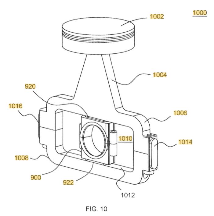
They *bought* the patent... it was granted in 2019 to an individual inventor then sold to Alfadan late last year. I'm pretty surprised at what's shown in the figure below. That's a crank driving a sliding bearing that changes direction (thus lacking hydrodynamic lubrication) under heavy load. Heck, at least my cams are unidirectional with high surface speed. If this is what they're doing, I'm surprised Mahle got involved. I think they would have spotted the lubrication problem right away.

Link
Capture_kbvqip.jpg
 
Yup, scotch yoke. As used in the Bourke engine.

Big problem is wear in the slippers at 922 and 920. The enormous reciprocating mass is also ungood. The curious thing is that it really isn't any better than balancer shafts, which are easy to lubricate and robust.


Cheers

Greg Locock


New here? Try reading these, they might help FAQ731-376
 
RodRico said:
They *bought* the patent... it was granted in 2019 to an individual inventor then sold to Alfadan late last year.
The original patent was filed by Alberto Francisco Araujo who is a director of Alfadan.

je suis charlie
 
Status
Not open for further replies.

Part and Inventory Search

Sponsor