Continue to Site

Eng-Tips is the largest engineering community on the Internet

Intelligent Work Forums for Engineering Professionals

  • Congratulations KootK on being selected by the Eng-Tips community for having the most helpful posts in the forums last week. Way to Go!

Applying Position Tolerance and/or Angularity to a Datum Plane 1

Status
Not open for further replies.

flash3780

Mechanical
Dec 11, 2009
829
Hello,
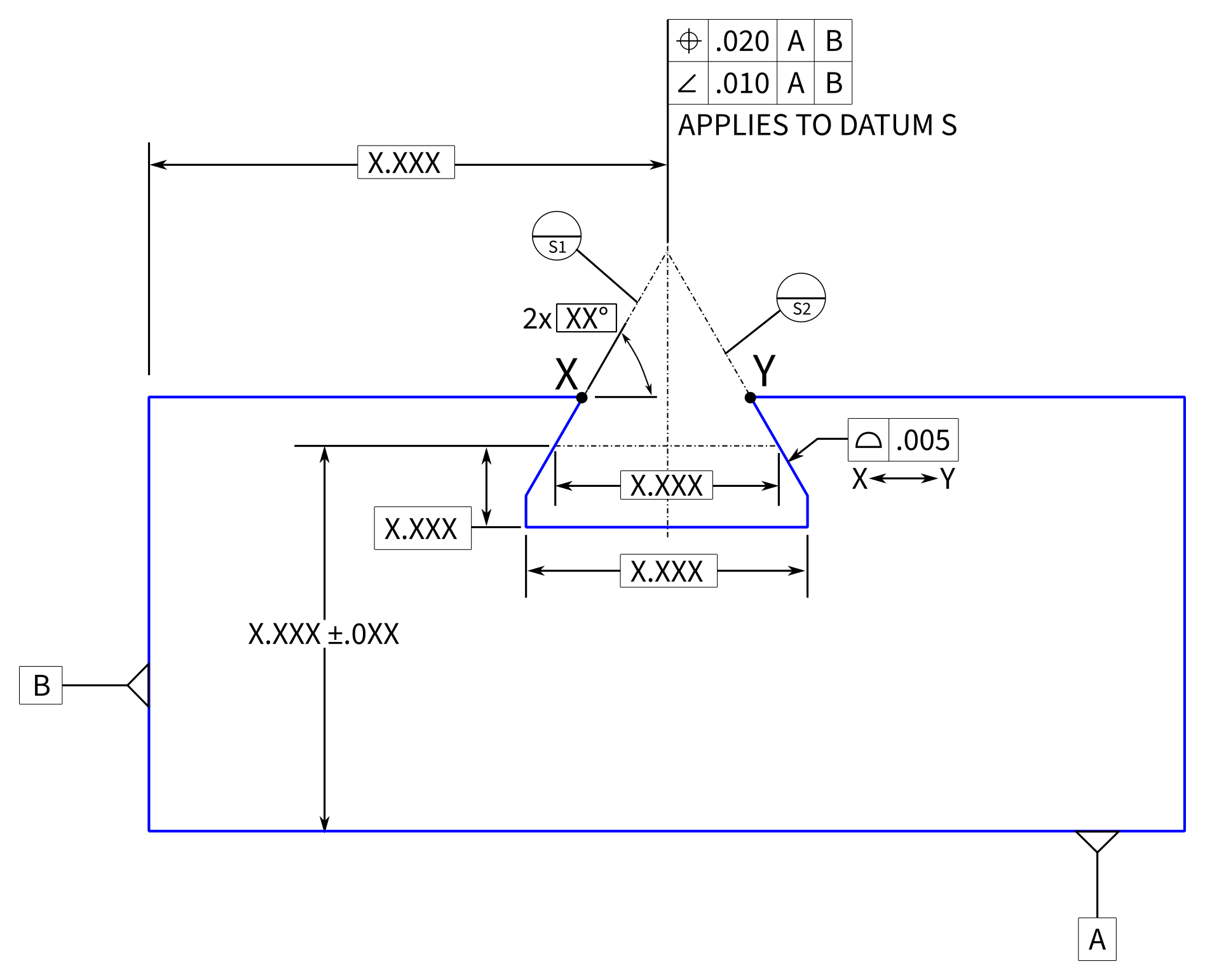
Been a while since I posted here. I've got a situation where I need to apply a position tolerance to the centerplane of a dovetail slot.

Since the dovetail slot is a complex shape and the functional part is tapered, I think that the centerplane of the slot is not entirely clear. So, I propose that I could use datum targets to establish the centerplane, and apply the position tolerance to the datum plane (see the note "APPLIES TO DATUM S" below). But, I wonder if that is clear?

I've made a simplified sketch of what I'm working with, and I wonder if there is a better way to accomplish it?

Thoughts?

-Chris

download.aspx
 
Replies continue below

Recommended for you

Maybe another option could be:
One surface datum feature A; the second surface datum feature B and an angular relationship-angularity- within some tolerance to A
Basic angle between those two surfaces.
In order to control the form error of datum features A and B, you could use two leaderlines such as 2X datumless profile within some tolerance

All other surfaces defined in relationship to A-B (common datum plane between A and B)


flash3780,

I would say that using datum targets to define something on the toleranced feature would be confusing to many people (it was confusing to me).

Rather than try to control the center plane (which Y14.5 does not define for a tapered slot), I would just use surface profile referencing A and B (in conjunction with the .005 profile tolerance with no datum features).

Was there a reason why you preferred to control the location and orientation of the center plane, and not the location and orientation of the slot surfaces?

Evan Janeshewski

Axymetrix Quality Engineering Inc.
 
Evan,
Thanks for the feedback.

The functional part of the slot is the taper, and the centerplane locates the mating part.

From a tolerance stackup prospective, I'd like to control the position/orientation of the slot centerplane directly, rather than indirectly with a profile tolerance on the tapered faces.

I'm updating an old drawing which has the tolerance applied to the centerplane, but does not define how the centerplane is established, so I'm wondering if I might be able to make it clearer. Hence, I was wondering whether adding datum targets and a note might clarify things.

If it were a square slot, it would be pretty straightfoward. The taper complicates things a bit.

The alternate approach that I thought about was to attach the position tolerance to the slot width dimension.

-Chris
 
Application of position tolerance to tapered features is a gray area that lacks direct support in the ASME Y14.5 standard. Specifically, the establishment of the 'unrelated actual mating envelope' to derive the controlled center plane or axis is not clear for anything but parallel plane tabs/slots, or cylinders.

But, you could try the approach shown in the example in the link below - using line elements to control the position of a tapered slot:
Link

 
Burunduk said:
But, you could try the approach shown in the example in the link below - using line elements to control the position of a tapered slot.

Thanks, that's along the line of what I was thinking for my second option. Alternatively, I think that I could write a note to describe how to establish the center plane.

I chatted with the inspector, and he installs "flags" into the slot to do the inspection. These are small metal gage fixtures which rest on the tapered faces of the slot. So, the position/orientation is measured relative to the "flags".

I think that this is what we want, but I don't know if there is a really clean way to specify it. I think my note below might capture that.


download.aspx
 
I think the position shall be applied to a feature (let alone to a feature of size) and the centerplane is not a feature!
Evan and Burunduk gave you a very good option.
 
greenimi said:
I think the position shall be applied to a feature (let alone to a feature of size) and the centerplane is not a feature!
Evan gave you a very good option. If you are not following the standard then IOIO (you are on your own)

What can I say: play stupid games, win stupid prices.

...except position tolerance is applied to a centerplane.
The problem is that it is typically applied to the centerplane of a feature of size.
Hence, I think a note might be appropriate, since a tapered slot is not a feature of size.

download.aspx


Sheesh man, no need to get uppity. I really do appreciate the help.

What I was trying to explain that the measurement that the current inspector is doing is functional, I don't want to change it.

I'm not trying to force him to change his inspection technique, but to clarify the drawing to be less ambiguous.
 
OP said:
I'm not trying to force him to change his inspection technique, but to clarify the drawing to be less ambiguous.

Then, if the product definition is your utmost importance use the tools available within the standard (Evan and Burunduk solutions) and it's alll risk management from there.
Inspection should not drive the show.
Is the dog wagging the tail or the tail wagging the dog?

In your latest sketch you applied/ attached the position callout to the centerplane with IMHO is incorrect.
 
flash, Look for the section on Feature Control Frame Placement. It does not include axes or center planes, leaving this application undefined.

The Y14.5 committee(s) has had 60 years to deal with positioning dovetails and chose to leave them out of the standard.
 
I think that I'm not being clear. I think that the recommendation in Burunduk's link is pretty much what I'm after.

However, I was thinking that a tapered slot is not a feature of size, and position tolerance must be applied to a feature of size per Y14.5. In the link, they claim that the slot width dimension is a feature of size. Is it?

When I read Y14.5-2009, I think that the tapered slot might be an "irregular feature of size" (1.3.32.2.b), so maybe I'm just confused. Seems like a gray area at best. Hence the reason I was asking whether a note might be a better approach. I compared to some similar parts, and they tend to use a note.

What's not clear to me is if I apply the position tolerance to the slot width, as in the link, will the centerplane be derived from faces of the taper? Or the discrete width? It seems like I need it to be derived from the faces of the taper, otherwise it's ambiguous.

The inspection that the quality department is doing is exactly the inspection that I'd like them to do.
It directly measures where the slot will position the mating part, so it's functional.

They've presumably arrived at the intended interpretation based on feedback from previous design engineers who worked on this part.

Anyhow, this is the inspection that I'm hoping to achieve (below).
download.aspx

 
Oh, OK, more clear - don't put any FCF or Datum Symbol on a centerline. There is no symbolic description available to perform the control you want in Y14.5

Creating a process description note is the only method available.

I expect, as is often the case, this method accepts useful parts but does not reject parts you don't want. As long as the machinists are producing useful parts you will never experience the difference.
 
flash3780 said:
What's not clear to me is if I apply the position tolerance to the slot width, as in the link, will the centerplane be derived from faces of the taper? Or the discrete width?

In the link, the author details how to control the center of the slot in the "gage line" (discrete width), not the center plane of the entire faces of the internal flat taper. As shown there in the image I linked to below directly, the position tolerance zone is 2 parallel lines. That tolerance zone lies on a plane defined by basic distance from the primary datum plane. It controls the center between 2 line elements. These can be considered as "a set of two opposed parallel line elements" from the 'regular feature of size' definition, (although this assumption can be nitpicked based on how one interprets the term "opposed" which is not covered in the standard).
To ensure correct orientation of the entire slot, the faces are controlled by surface profile with ref. to the datum feature used as the primary for the position control.

image
 
flash3780

Expect this figure will give you some idea on the dimensioning and control of a tapered slot surface(surface S and surface T on your case).

2023-01-07_qvkozd.jpg


Season
 
It looks like that diagram allows for an interference fit between those two parts. This is the nominal geometry with the line width representing the profile tolerance. If the tab moves enough to clear the bottom of the slot the sides of the tab may interfere. There was enough room for side-to-side tolerance, but not on the depth.

It also suggests an ambivalence of having a fit that traps the tab between the wedge and the top surface to limit vertical movement or between the bevel and the bottom of the slot. If the latter, there is a gap that is forced at the upper horizontal interface so that any vertical load is taken only by the small flats.

dovetail_ilxxri.png


It would have benefited from using unilateral profile tolerances.
 
Burunduk said:
In the link, the author details how to control the center of the slot in the "gage line" (discrete width), not the center plane of the entire faces of the internal flat taper. As shown there in the image I linked to below directly, the position tolerance zone is 2 parallel lines. That tolerance zone lies on a plane defined by basic distance from the primary datum plane. It controls the center between 2 line elements. These can be considered as "a set of two opposed parallel line elements" from the 'regular feature of size' definition, (although this assumption can be nitpicked based on how one interprets the term "opposed" which is not covered in the standard).

I agree with this interpretation, but this is slightly different than the inspection that they're doing today: expand a centralizing mandrel inside the slot until it touches the angled faces, 10 mm from surface A and find the centerline.

Actually, I prefer to use profile tolerance, as suggested by SeasonLee. I think that is the most reasonable approach.
A compound profile tolerance would control form and orientation separately. Or multiple profile tolerances referencing different datums could control movement relative to those datums independently.

However on this particular blueprint, it is a legacy part. The company has inspected the profile of similar dovetails via optical comparator for at least 75 years, and separately inspected the location in a similar method to what I drew. I'm not intending to change the inspection method on this particular part. So, I think a note is warranted here.

The impetus for the change is to digitize this old blueprint and correct some conflicting requirements (which are confusing). As it turns out, manufacturing and quality are doing the right thing, but the drawing is in need of some love. I'm trying to correct the errors and digitize the print without changing the actual inspections, if that makes sense.
 
flash3780,
Yeah, your goal makes sense - not fixing what's "not broken".
But you may end up having to specify the inspection method in the drawing or in an additional document, because the standard doesn't give you a way to say what you're trying to say.
BTW, why do they use an expanding mandrel, rather than a fixed gage with just the exact taper angle (the basic angle), pushed up against the slot faces?
 
Burunduk said:
BTW, why do they use an expanding mandrel, rather than a fixed gage with just the exact taper angle (the basic angle), pushed up against the slot faces?
Sorry, I should have been more clear. They currently use a fixed gage to derive the center. I was saying that the method you suggested would require a expanding mandrel, so it'd be a bit different.
 
Status
Not open for further replies.

Part and Inventory Search

Sponsor