Continue to Site

Eng-Tips is the largest engineering community on the Internet

Intelligent Work Forums for Engineering Professionals

  • Congratulations KootK on being selected by the Eng-Tips community for having the most helpful posts in the forums last week. Way to Go!

Appropiate MMB boundary 1

Status
Not open for further replies.

Ivan Silva

Industrial
Dec 13, 2019
45
The ASME Y14.5 - 2018 says some words about choosing the appropiated MMB boundary: "7.11.6 The appropriate MMB for determining the size of the true geometric counterpart for an external datum feature(s) of size is the smallest MMB that can contain the datum feature(s) of size while respecting the datum feature precedence.

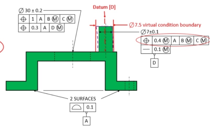
About this I think I couldn't understand what does it means with datum precedence when choosing which geometric tolerance must be take account on MMB calculation. See the image below:
SmartSelect_20220614-201455_Samsung_Notes_ac1vhj.jpg


Focusing only on datum D from the mid big hole. The FCF says datum D MMB must be located or oriented to datum A (perpendicularity in this case). So when choosing which geometric tolerance must be taken account to calculate MMB must I search for geometric tolerances applied to datum feature D which also refeers datum feature D perpendicular to datum A? Is that what the standard calls "features precedence"?

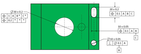
Another complementary image just for reference:
Capture_f135a9.png
 
Replies continue below

Recommended for you

What is the source of the figures?
Looks like training material, but I don't know why the diameter symbol is not used before the position and derived median line straightness tolerance values for cylindrical features.

To answer your question, what you need to consider when calculating the MMB size is: what are the allowed variations in orientation, location, or both - for the specific datum feature, relative to the higher precedence datums as they appear in the feature control frame that applies to the considered feature that references this specific datum feature.

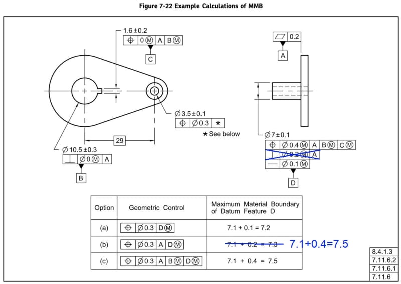
For example, when calculating the MMB of datum feature D for the 0.3 position tolerance control that references A primary, D(M) secondary, you have to consider the allowed variations of datum feature D relative to datum A. The 0.4 positional tolerance applied to datum feature D, which in this case also encompasses the maximum orientation error relative to datum A, provides a value to be added to the MMC size for the above-mentioned MMB calculation: MMB = MMC+Position tolerance = 7.1+0.4=7.5. This MMB value will be the size of the true geometric counterpart or datum feature simulator for datum feature D for the A, D(M) datum reference frame.
 
Burunduk said:
which in this case also encompasses the maximum orientation error relative to datum A
May I understand this way: If we remove the perpendicularity callout from Fig.7-22 2018 Ver. (this will be the same as OP's figure), then the MMB for option (b) and (c) will be the same as shown below. Am I right?

Fig_7-22_2018_k2poa0.jpg


Burunduk said:
What is the source of the figures?
I am also curious to know which book or training material is this figure from?

Thanks
 
Now I got it. Thank boys. About the diameter on position tolerance zone I think it was missed. About the book it’s from Dave Slopsema who hosts the dimensional consulting web site.
 
@SeasonLee

I just finish the reading of the topic you suggest. It was enlightening. About the Drafting Zone website is it down or the hosts only changed it's domain?
 
The old Drafting Zone website appears to be toast. RIP DraftingZone
 
Ivan Silva said:
About the Drafting Zone website...
No idea what's going on, but I noticed they didn't make any updates on their website for a long long time.

Thanks
 
Status
Not open for further replies.

Part and Inventory Search

Sponsor