Eng-Tips is the largest engineering community on the Internet

Intelligent Work Forums for Engineering Professionals

AS 3600 AMDT 2 Equation 8.2.7(2) -continuing a previous thread

Status
Not open for further replies.

kww2008

Structural
Feb 1, 2008
149
0
16
AU
The thread744-499791 is closed. To continue discussing, I created this new thread.

In a former posting by Doug (IDS(Civil/Environmental)in the thread, he stated:

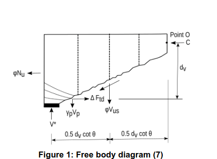
"Case 3 is just using the AS5100.5 code formula for the longitudinal force due to shear, and finding the adjusted bending capacity, allowing for the force. Increasing the shear reinforcement reduces the longitudinal force, so increases the bending capacity."
as a response to my query:
"Could you please describe the steps in your calculation for Case 3 which resulted in an increase in bending capacity from an increase in the area of shear reinforcement ?"

My understanding of the analysis described in Doug's blog (link provided in thread744-499791) is as below.

The total longitudinal steel A[sub]st1[/sub] is first determined for shear reinforcement A[sub]sv1[/sub]/s for a section with design shear V*[sub]1[/sub], ultimate shear strength V[sub]u1[/sub] such that the axial force in A[sub]st1[/sub] is close to f[sub]sy[/sub] under combined action effects M*[sub]1[/sub] and V*[sub]1[/sub]. The shear reinforcement is the increased to A_[sub]sv2[/sub]/s with the following values kept the same:
V[sub]u2[/sub] = V[sub]u1[/sub],
V*[sub]2[/sub] = V*[sub]1[/sub]
A[sub]st2[/sub] = A[sub]st1[/sub]
A new moment effect M*[sub]2[/sub] is then determined through trial and error (or iteration) so that A[sub]st2[/sub] is close to f[sub]sy[/sub].
Owing to M*[sub]2[/sub] determined being greater than M*[sub]1[/sub], it was concluded that an increase in the shear reinforcement caused an increase in "reduced moment capacity"

Doug,
Before I discuss further, I would like to check whether my description of the analysis above is accurate.
 
Replies continue below

Recommended for you

I disagree with kww2008's post to an extent.

Imagine a situation where the design actions on a particular beam are very small, say V* ~ 0 kN and M* ~ 0 kNm, just for argument's sake.

Now take the exact same beam and apply some substantial combination of V* >> 0 and M* >> 0, perhaps near the brink of shear failure.

According to the MCFT formulation in the Australian codes, which calculate epsilon_x, k_v and theta_v based on the ULS design actions (V*, M*, N*, etc.), these two beams would be predicted to have two completely different shear strengths, which is impossible. I understand the Australian codes don't want to get into the iteration process because it becomes very unwieldy, but in my opinion it needs to be done.

For design purposes, at best, you can use the ULS design actions to satisfy V* < phi*Vu, but merely satisfying that inequality will only give a lower bound on the shear capacity, and may give the impression that there is more reserve capacity than there actually is. For a load rating exercise of an old bridge, on the other hand, using the ULS design actions to calculate the shear strength of a beam may give an overly-conservative estimate of its shear strength, because you may be assessing the beam for a combination of loads that it can't actually reach. In this case, you would have to scale the design actions down.

In my opinion, the shear strength of a concrete beam is simply the shear force that it can resist right up to the brink of shear failure. It has nothing to do with the magnitude of the design actions, only their ratios (e.g. M*/V*, N*/V*, etc.). I believe the iteration approach is given more consideration in AASHTO for example.

As a side question, I am interested to know everyone's approach when it comes to iteration. Do we try to match V* and phi*Vu directly, or are we trying to match V* and Vu, then apply the phi factor separately after the iterations are complete? So far I have been leaning towards applying phi after the iterations, but there has been some debate each way in my office. I understand that applying phi after the iterations tends to give (very) slightly more conservative results, though probably nothing meaningful.
 
Actually, CFT and MCFT and SMCFT (which is actually the codified version in several codes, AS, CSA, AASHTO), is based combined moment and shear actions on, initially a small elements withing the 3D beam member, and by the time it gets to SMCFT, the combined moment and shear actions on a section.

So the concrete shear capacity, Vc is dependent on both the co-existing moment and shear actions on a member and will be different for every load condition.

The problem with older code shear design methods was that they were basically independent of flexural effects. So a member with the same design shear, but very different moments had the same shear strength if they had the same flexural reinforcement, even though the principal strains were very different. So a section at the free end of a member where M is basically zero had the same capacity of the critical section at the face of an internal support with a large M if the flexural steel quantities were the same.

MCFT recognises that the very different principal strains in these 2 cases gives very different principal stress and therefore very different concrete shear capacities.

In older design methods for PT, most codes required a principal shear design check as well as a flexural shear design check. But not for RC members. MCFT combines them into one shear check, but they are dependent on M and V.

SMCFT introduced a simplified expression for determining the principal strains due to this combination to make application of the theory codifiable and more simple to use (if you every looked at even the initial MCFT it was basically impossible to apply in a design situation, CFT was impossible) which is in the codes (Epsilonx in AS3600), but I think all codes then allow the designer to determine the strains by more rigorous methods. The strain calculated in SMCFT is basically at the point when the flexural steel reaches Yield, not at ultimate.

We have been saying for years that a more logical approach considering the combined flexural and shear actions was needed. MCFT provides that and is by far the most logical method of determining shear capacity in the design phase which is why codes are adopting it.

This may present problems for people trying to do the reverse and are attempting to determine a load rating for an existing structure. But that does not mean there is a problem with AS3600 or other design codes that have adopted the solution for the design of concrete structures.

Maybe codes used in areas where load ratings are required to be calculated on a regular basis should introduce a method for doing this. Or engineers doing load rating exercises need to go back to the fundamental principles of CFT and determine a methodology based on that for themselves.

 
bugbus - I think everyone is agreed that if you want to check if a given section is adequate for a given M* and V* then you don't need to iterate, but if you want to find the actual section capacity for a given ratio of M*/V* then you do need to iterate.

My main points in this thread were:
1) The current procedure in AS 5100.5 can be un-conservative.
2) The procedure in AS 3600 complies with the MCFT it is based on, and is not over-conservative if applied with adjustment of Theta where necessary.

kww2008 seems to disagree with one or both points, but so far it isn't clear to me why.

Doug Jenkins
Interactive Design Services
 
Thanks Doug, I admit I didn't read the thread in its entirety earlier, but I will now.

I have just realised that in the Draft Amendment 2 for AS 5100.5, there is a new statement in Clause 8.2.4.1: "For the calculation of the capacity of a predefined member and the assessment of members of existing structures, iteration shall be used to determine the value of the longitudinal strain (epsilon_x)."
 
More details of the section used for the graph I posted on 17th Sep:

Cross section and longitudinal steel:
Longshear1_xocbb3.jpg


Shear steel and applied loads:
Longshear2_hp4x7f.jpg


The only inputs that were changed were:
The shear steel diameter.
For AS 3600 with adjustment of Theta the "Compression Strut Angle" was adjusted to reduce the shear capacity to 280 kN, with a maximum of 50 degrees.

For AS 3600 the moment capacity results were multiplied by 0.8/0.85 so that they had the same Phi value for bending as AS 5100.5

The spreadsheet used for the calculations can be downloaded from:
[URL unfurl="true"]https://interactiveds.com.au/software/RC%20design%20functions9.zip[/url]

Doug Jenkins
Interactive Design Services
 
Thank you Doug for the information. What is the Vu from using the input above ? When I used this value in my spreadsheet, using equations in AS 5100.5, my theta_v is less than 50 degrees. The value phi_v shown is 0.7. Should not this value be 0.75 since more than Asv.min provided ?
 
Vu values are:
Dia, mm Phi.Vu, kN
10.0 274.6
12.0 350.8
14.0 440.8
16.000 544.6
20.0 793.9

Yes, ThetaV is 37.56 degrees. That is why it can be adjusted when using the AS 3600 provisions.

I have just used the lowest possible Phi values across all the codes, to keep everything the same, other than the equation for longitudinal force.


Doug Jenkins
Interactive Design Services
 
IDS said:
I think everyone is agreed that if you want to check if a given section is adequate for a given M* and V* then you don't need to iterate, but if you want to find the actual section capacity for a given ratio of M*/V* then you do need to iterate.

Disagree that there is an "actual section capacity" for a section subjected to a given M*/V*. According to MCFT, there is no "actual section capacity" for this section. There are multiple section ultimate shear strengths, each corresponding to a different level of V*. There is a phiVu for V*=phiVu. This ultimate shear strength has optimal shear adequacy (ie. V* is not greater or less than phiVu) for the corresponding level of design shear V*.

Iterations are only required to determine shear=strength for investigative studies relating to MCFT where a test to failure is carried out by applying a monotonic load, and not necessary for design or load rating. Iterations is often used to seek the level of shear loading Vun = Vn for tests. Vun the the shear level we expect to see signs of shear failure. We use mean material strengths obtained from testing and to exclude all safety coefficients. The subscript "n" shows the use of unfactored values. At intermediate levels of shear(Vn < Vun), we can check accuracy of the equation using strain measures since no visible shear distress is expected.

To show the inappropriateness of using a phiVu determined for another level of loading for the calculation of load rating factor for shear, let us look into the meaning of V*= phiVu. phiVu is smaller than Vun as it has safety factors (from using φ, characteristic values for steel and concrete). V* is larger than Vn (from using load factors). Thus, phiVu has moved to the right on the magnitude line and Vn to the left. Since these values have safety coefficients included, V*= phiVu has meaning only for shear adequacy to the standards. phiVu (=V*) is the reduced ultimate shear strength at V* (for this monotonic load) for optimal (not more or less than required for the level of safety of the standards) shear adequacy. It is not an "actual shear capacity).

Since the MCFT equations in AS5100.5 and AS3600 are expected to be accurate, and safety coefficients have been included as required by standards, the phiVu calculated using M* and V* (without iterations) for the most critical (expected to give lowest factor for the bridge) vehicle position is suitable for calculating load factor for shear. Also the use of phiVu determined without iteration is consistent with rating the loading of the nominated vehicle on a bridge as intended in AS 5100.7. When we iterate, the phiVu determined is for a scaled vehicle.

By using the phiVu determined without iterations, the load rating factor determined gives an accurate measure of the degree of shear adequacy for the bridge vehicle system. Using the strength from iteration, on the other hand, will not give an accurate measure since the strength is not consistent with the design actions M* and V*, and with the load.
 
There is a lot I don't agree with there, but to keep things focussed on the topic of the thread I will change my statement quoted above to:

I think everyone is agreed that if you want to check if a given section is adequate for a given M* and V* then you don't need to iterate.

It seems you also agree that the equation for the longitudinal force in AS 5100.5 is unconservative, because you agree that Phi.Vs should be limited to V*, as in the AASHTO and Canadian codes.

The only outstanding question is the validity of the AS 3600 equation. When Phi.Vu = V* it exactly agrees with the AS 5100.5, and with adjustment of the Theta angle it is not over-conservative when Phi.Vu > V*, in fact slightly less conservative than the American versions, so I still see no problem with it.

Doug Jenkins
Interactive Design Services
 

When we changed over from using an ultimate shear capacity which depends on action effects, the relationship between strength and shear is nonlinear. While the load rating factor can be taken as a load scaling factor (to determine the ultimate shear from design shear) in the past with earlier design standards because of usage of a non-varying strength with shear, this is no longer the case when we use MCFT to determine shear strength. Not using iterations gives a rating factor for the rating vehicle. Using iterations (on the live load component only) gives a scaling factor (such that the scaled vehicle has a load rating factor of one). Note that the scaling factor is not a rating factor.

The load rating factor should continue be determined without the use of iterations. This is the current practice and should not be changed in AS 5100.7 as the load rating factor gives an accurate measure of shear adequacy. If a scaling factor (applied to the rating vehicle to give a scaled vehicle with a load rating factor of unity) is required, that should be requested by individual road authority owning the bridge since they are the users of the rating information to manage bridges.

_______________________________________________________

Doug,

Thank you for your comments.

IDS said:
It seems you also agree that the equation for the longitudinal force in AS 5100.5 is unconservative, because you agree that Phi.Vs should be limited to V*, as in the AASHTO and Canadian codes.
I agree with including a restriction "The term phiVus should not be taken to be greater than V*" . Designers can still use phiVus > V* for section shear design.

IDS said:
The only outstanding question is the validity of the AS 3600 equation. When Phi.Vu = V* it exactly agrees with the AS 5100.5, and with adjustment of the Theta angle it is not over-conservative when Phi.Vu > V*, in fact slightly less conservative than the American versions, so I still see no problem with it.
This should be changed to using phiVus to be consistent with the equations in other national standards and to add the restriction above.


This should be changed to using phiVus to be consistent with the equations in other national standards and to add the restriction above.

I strongly disagree. AS 3600 is already consistent with MCFT, and gives results that are consistent with the N. American codes based on MCFT.

AS 5100.5 is currently under final stages of revision following public comment. It needs to be revised and should be revised to use the same equation as AS 3600, so the national concrete codes are consistent on this issue.


Doug Jenkins
Interactive Design Services
 
If you look at the ASSHTO force diagram, you have to maintain horizontal force equilibrium,vertical force equilibrium and rotational equilibrium (except they forgot to add the moment etc).

In their model,( assuming it is complete even though we disagree), The only vertical forces are Vu, Vs and Vc (which for some reason you think you can ignore).

The whole derivation if done properly requires

Vu = Vs + Vc .

You cannot then ignore part of this in deciding on the Vs limit. You cannot create vertical force. You cannot ignore one force. If you put in more vertical steel, the stress in the steel reduces. The force stays basically the same to maintain vertical equilibrium. The vertical reinforcement cannot attract more force than exists.

Just because 2 other codes have decided to ignore statics does not mean we should. Otherwise other designers around the world could be saying " but AS5100 says Vs is unlimited" so it must be.

Do we then accept that as correct?
 
Doug,

Agree to disagree with "It needs to be revised and should be revised to use the same equation as AS 3600". Thank you for your comments.
 

rapt said:
The whole derivation if done properly requires

Vu = Vs + Vc .

Suggest you get hold of a recent copy of AASHTO bridge Specification to view the diagram and the assumptions made, and to see the equation is derived. In AASHTO 2010 5th Edition, this diagram has a label "Forces Assumed in Resistance Model Caused by Moment and Shear". An assumption is made that Vc (which is acting along the assumed diagonal crack) has a negligible moment (owing to having a small lever arm) about point 0, a point near the top of the diagonal crack.

The failure mode of interest is rotation of the block, so Vu = Vs + Vs (the requirement for section shear) has no relevancy to this "determination of the requirement for tension force in the longitudinal reinforcement". Section shear is a mode which has to be designed for separately.


rapt said:
If you put in more vertical steel, the stress in the steel reduces.
The calculation of longitudinal force in the longitudinal reinforcement is based on the assumption that the full resistance from the vertical steel Vs (yielded) is mobilised and the acting force is Vu. If the vertical steel is not at yield ( if excess vertical steel is provided), that does not invalidate the use of the model because failure in this mode requires both the horizontal and vertical steels to have reached yield. That is why one has the flexibility to adjust the amount of vertical steel provided and the amount of horizontal steel required.


The figure of the block shown in the Concrete2023 conference (reference given above) by Vimonsatit, Wong and Mendis (2023) is reproduced below. Note the typo error - label V[sub]p[/sub] should read P[sub]v[/sub].
Figure_1-_Concrete2023paper_sgmyn8.png
 
Bugbus said:
As a side question, I am interested to know everyone's approach when it comes to iteration. Do we try to match V* and phi*Vu directly, or are we trying to match V* and Vu, then apply the phi factor separately after the iterations are complete? So far I have been leaning towards applying phi after the iterations, but there has been some debate each way in my office. I understand that applying phi after the iterations tends to give (very) slightly more conservative results, though probably nothing meaningful.

If you iterate using the live load portion V*(LL) only and match the varying V*(DL+LL) with phiVu to give phiVu(iteration), the factor determined using V*(DL&LL) (design shear), phiVu(iteration) and V*(DL) is a scaling factor. This factor applied to the full vehicle gives a scaled vehicle with a load rating factor of one (no iterations). If not convinced that the factor obtained is a scaling factor for a scaled vehicle with optimal shear adequacy, you can carry out simple analyses to verify this.

Using a phiVu (no iterations) consistent with the load of the rating vehicle, the factor calculated using the rating equation satisfies the definition of rating factor in AS5100.7. This factor is correct as it gives an accurate measure of the degree of adequacy for section shear. It is useful even for phiVu < V* as it shows the degree of under-strength. A scaling factor does not give this information. Additionally, determining scaling factors for rating vehicles with fixed axle loads, eg. SM1600 and T44 does not make sense as the scaled vehicles do not represent real vehicles. Also, scaling variable axle loads of a platform of a road train changes fixed axle loads of its prime mover.


To ensure compliance with MCFT, the strength must be consistent with the applied load. Since you are trying to get optimal adequacy (V*=phiVu) for a scaled vehicle, the Vu used must be for the same loading (i,e, V*,M*). Matching V* with phiVu gives a scaled vehicle with optimal shear adequacy (i.e, V* equals phi.Vu(V*,M*)).

It is not possible to get V*=phiVu if you iterate to satisfy V*=Vu(V*,M*), and then apply phi.
Scenario V*= Vu, say 10 =10, phiVu is 7 with phi=0.7. Therefore V* will always be less than phiVu.

In a design situation, to satisfy V*=phiVu for (M*,V*), the Vu(V*,M*) calculated using V* and M* has to be larger than V*. Not easy to visualise as they are factored values and we are dealing with nonlinear behaviour. Maybe, Vu=V* has no specific meaning in design and load rating since they are factored values.

Summary
To determine a scaling factor when applied to the rating vehicle gives adequate shear for the scaled vehicle, use the reduced strength obtained by iterating the live load to meet the requirement phi.Vu(M*,V*)=V*.
 
Bugbus,

My post above is consistent with how we do design now. For a set of (V_d*,M_d*) calculate V_ud, so this Vu_d is consistent with M_d*/_dV*. check whether V_d*=phiV_ud if we want optimal adequacy. So we have consistency since M_d*,V_d* and phiV_ud is for the same level of loading.

I am able to understand now how you can determine phiV_u by matching V* with V_u when not considering the iteration as scaling the vehicle to get an optimal scaled vehicle for shear. Iterate V* maintaining ratio M_d*/V_d* till V_u = V*. Then determine phiV_u. Doing this way is not using the iterations to scale the vehicle to get optimal adequacy. This way of calculating phiV_u is assuming a fictitious loading path of M_d*/V_d* to determine phiV_u. If you do it this way, a new design with optimal adequacy (using the current design method) will not give a factor of one.

The load rating factor we get using AS 5100.7 gives an accurate measure of shear adequacy, consistent with MCFT. (V_d*,M_d*) is just a point on the MCFT interaction diagram. It cannot be used to scale the load to check if a scaled vehicle has adequate ductility owing the nonlinearity in MCFT. Therefore, in addition having this rating factor, having a scaling factor is useful for vehicle-bridge systems with critical shear from a set of variable axle loads. A new bridge with phiVu_d = V_d* gives a rating factor of unity as expected.

If the iteration is not a numerical method to scale the vehicle for adequacy, then matching V*=phiVu may not be suitable. Unless we know the reason for using the numerical procedure (iterations) to determine strength, difficult to decide which approach is suitable.


Bugbus,

If you iterate using the live load portion V*(LL) only and match the varying V*(DL+LL) with Vu to give Vu(iteration), the factor determined using V*(DL&LL) (design shear), Vu(iteration) [Use this Vu to replace phiVu in the load rating equation] and V*(DL) is a scaling factor. This factor when applied to the full vehicle gives a scaled vehicle, and this scaled vehicle (on the bridge at the same position as the full vehicle) gives a load rating factor less than one (no iterations). Iterating this way does not give any useful information since the scaled vehicle does not give optimal shear adequacy.

If not convinced that the factor obtained is a scaling factor when applied to the full vehicle gives a scaled vehicle with less than optimal shear adequacy,you can carry out simple analyses to verify this.


kww2008

Just been looking at the latest FIB Model Code 2020 in its shear section.

They appear to be making the same mistake as us in AS3600, requiring horizontal and vertical force equilibrium as well as rotational equilibrium.

They have exactly the same equation for longitudinal tension force from shear as AS3600-2018 Amendment 2 for their Level III result, which is based on MCFT, in equations 30.1-30 and 30.1-31!

deltaT = .5(Ved + Vrd.c) cot (theta)

when you combine the 2 equations!

 
Rapt,

The equation for additional force with the term φV[sub]us[/sub] in longitudinal steel caused by shear in Clause 8.2.7 of AS 3600-2018 with Amdt 1 and AS 5100.5-2017 with Amdt 1 is not based on MCFT. This can be seen in previous published papers mentioning this equation.

In the paper "Background to the general method of shear design in the 1994 CSA-A23.3 standard" by Khaldoun N. Rahal and Michael P. Collins, Canadian Journal of Civil Engineering Volume 26, Number 6, December 1999, they stated that "Collins et al. (1996) and Collins and Mitchell (1991) calculated the longitudinal force at a cracked section due to the shear force as cot θ (V[sub]f[/sub] – 0.5V[sub]s[/sub] – V[sub]p[/sub])."


The first cited reference is a published paper:
Collins, M.P., Mitchell, D., Adebar, P.E., and Vecchio, F.J. 1996. "A general shear design method", ACI Structural Journal, 93(1):pp 36–45.

The second cited reference is the book:
Collins, M.P., and Mitchell, D. 1991. Prestressed concrete structures. Prentice-Hall, Inc., Englewood Cliffs, N.J.

I do not have access to a copy of the book and will try to get hold of a copy to see the calculation. I think the calculation is similar to that described in the first cited reference.

The first cited reference shows how this equation is derived. It is not based on MCFT which is the theory for the determination of shear strength for a section subjected to a set of load effects. The MCFT-based equation used for design is applicable to section behaviour only, not block behaviour. As shown in the first cited reference, the equation for force is derived using a free body diagram of a block of concrete with a diagonal crack (similar to the one used in AASHTO). While this equation is quite often mentioned by researchers in technical papers on design for section shear using MCFT, it is not based on MCFT.

I cannot comment on the equation in the model code since I do not have access to a copy. In your posting, you mentioned that the equation is based on MCFT. This suggests that the force in the model code (for section behaviour) is not the same as that used in the AASHTO standard, AS 3600 Amdt1 and AS 5100.7 (for block behaviour).
 
Status
Not open for further replies.
Back
Top