Eng-Tips is the largest engineering community on the Internet

Intelligent Work Forums for Engineering Professionals

AS 3600 Cl 10.8 Transmission of Axial Force through floor systems

Rav01

Structural
Sep 3, 2024
4
0
0
AU
Hi guys,

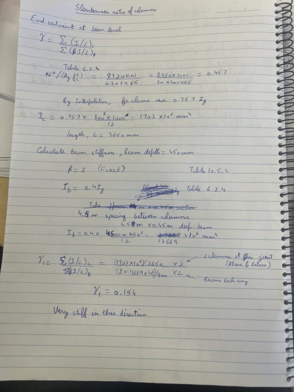
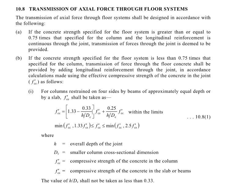
I am designing some 65MPa columns above and below a 40MPa slab. Referring to the Cl 10.8, it is a bit confusing to understand. Since I have to comply with (b) part of this clause, I have calculated my f'ce = 55MPa. It is a bit unclear whether this is the maximum compressive strength that I can use for the full height of my column or is it only for the section getting sandwiched in between. If it is just the slab section in between, why would I need any extra reinforcement? My slab is 400mm deep and 300x1000 columns. So, that small section of concrete should definitely work with the reinforcement that I am providing for the columns for the axial load that is getting transferred from above column to below.

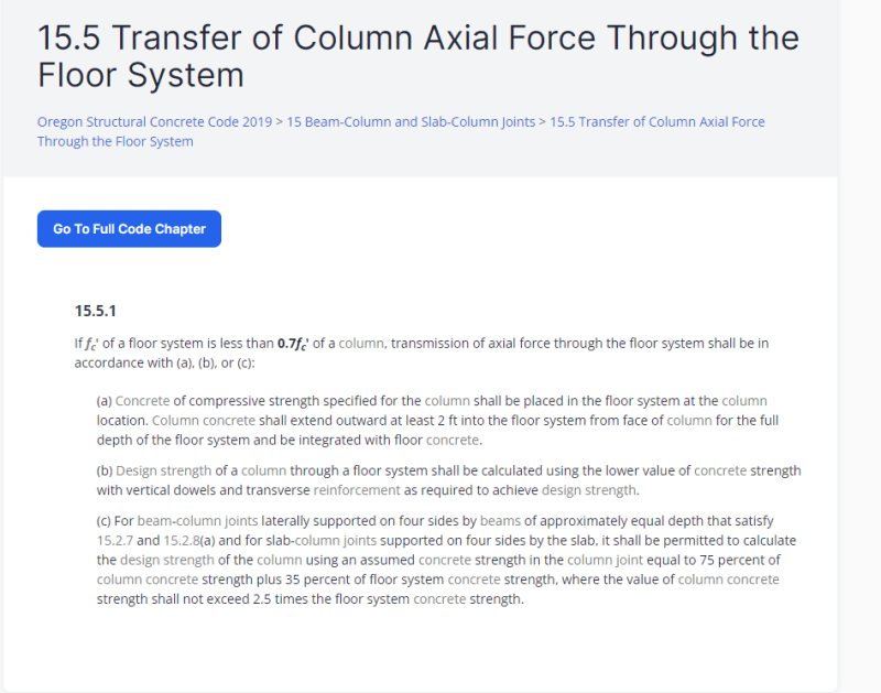
ACI code says that I can use 75% of column strength + 35% of slab strength which is 62.5 MPa in my case.

Please let me know what your thoughts are on this.


AS3600_Cl_10.8_gnkcl5.png


ACI_Cl15.5_dxbgjb.png
 
Replies continue below

Recommended for you

The f'ce you calculate is just for the sandwiched section of slab.

You may need additional reinforcement, at the column-slab junction, if your axial on the columns and being transfer through the slab is greater than 9880kN (using your 300x1000 column with about 1% reinforcement). Your slab strength is calculated using the squash load (phi Nuo) for a section the same size as the column using the calculated f'ce with whatever reinforcement is present in the column.
 
I'm not fond of using the squash load for transmission through the slab. If the column above and the column below are both having to account a minimum moment, the section confined inside the slab should be transferring that minimum moment through.

----------------------------------------------------------------------

Why yes, I do in fact have no idea what I'm talking about
 
Thank you for that guys. Makes sense.

The issue is for some of these columns, I have got the above column at 90 degrees, which means I cannot get all the bars through from the bars under. I am thinking about putting a 750mm deep drop panel so that I can develop my 12N32 bars in compression, 700mm. What would be the sandwiched section is this case? Surely, the whole drop panel will be engaged and I can design the drop panel as a strut and tie to transmit the forces from the column above to below.

Also, I am using k=0.7 for these columns and will be designing the pad footings for bending moment from the column.
 
The issue is for some of these columns, I have got the above column at 90 degrees,

I wouldn't be designing this as a "transmission through" case, the load is being applied to the slab and the slab has to transfer the load to the column. You might be able to take the overlapping region as a a portion of the load transferring through and putting the remaining load to the drop-panel and design accordingly

k = 0.7 feels very unconservative for me however, I'd avoid if possible. Hard to justify the rotational stiffness of the pad footing, has a heavy reliance on geotechnical behaviour for stiffness. Between two slabs you can do the manual calculations to get your k values based on relative column to floor stiffnesses
 
aah yep that makes sense. I have done some calcs and tried to make it work without taking any rotation into the pad. I was able to get gamma as 0.15 for slab and if I consider gamma for pad footing as 10 which means no rotation, I am still getting k=0.725 if my calcs are correct. My slab above is way longer but I have only considered 4.5m being conservative.

Image_y3ypzz.jpg
Image_1_ynvzvu.jpg
 
You have made a mistake with you effective length gamma factors. Look at figure 10.5.3(A). 0.7 is fixed fixed. You can't achieve that with a pad footing, and a slab on one end can't provide equivalent stiffness of two fixed ends. At best you can achieve 0.85, probably higher with a rotating column over.

This isn't an axial transmission issue, it sounds like a slender column design issue.


Hi BentEng,

Thank you for your reply. What you are saying makes sense that we can’t have two sides fixity 0.7 just from the slab. However, I looked at commentary and it says that that figure is just an approximation where fixed ends are allowed a bit of rotation. That is why I used the stiffness method to get the fixity of the column at the slab end and my gamma value is 0.15 as per my calcs above unless I did something wrong.

Secondly, yes I agree that it is an issue that I have a perpendicular column above and my bars from bottom column will not develop. However, to counter this, I will be putting in a 750 deep drop panel so that the bars from bottom column can develop 700mm. Min. compression development length for N32 bars. Then, I’ll have to design the pad as strut and tie to transmit the load from the column above.


What are your thoughts on this?
 
My thoughts are that you're grasping at straws to justify k=0.7, when it clearly can't be achieved. I suspect you have a calculation error in your gamma factors. The figure is approximate - so is the stiffness calculation. You have no idea what the true stiffness of the slab/column/footing is, so it never makes sense to use such an aggressive k factor, unless it's a thin column wedged between two deep beams - something that clearly provides near full fixity to each end.

The fact that you have multiple issues here (column, joint) points to the structure being inadequately sized.

Unless it is already built, it's never too late to increase the column size (and even then I've had to post-build increase a column size).
 
I cannot directly assist, though the the AS 3600:2018 Sup 1 includes a discussion, that includes the following reference: OSPINA C.E., ALEXANDER, S.D.B., Transmission of High Strength Concrete Column Loads Through Concrete Slabs, Structural Engineering Report No. 214, Department of Civil Engineering, University of Alberta, Canada, 1997.
 
@Rav01
I see a few issues in your k-value calculation.

1. you apply a stiffness reduction to the column. However, these are intended for lateral resisting elements (so they should be applied when analyzing lateral loads, not gravity loads), and it's unconservative for the k-value calculation to reduce the column stiffness. You should leave the column stiffness as 1, as under gravity loads the columns will be fully uncracked.
Likewise, for your slab, the modification factor you used is intended for lateral resisting elements. However, 0.4 seems to be a fairly conservative value, so it may be acceptable in this case. I usually use between 0.25 and 0.35 for spanning members assumed to be cracked (unless they are PT).

2. You are ignoring the Young's modulus of the concrete in the column and in the slab. It will be higher in the column and lower in the slab. Ignoring this assumes the Young's modulus is the same, which in your case is unconservative (because the column has a higher concrete grade).

3. Using beta = 2 seems unconservative. I usually use 1 unless you really have a fixed connection or something extremely stiff, like a large shear wall parallel to the beam or slab. I'd suggest using 1.

In your case, adopting the above, I calculate a gamma1 = 0.76.
Associated with the gamma2 = 10 from the footing, your k-value is just under 0.85, which agrees with the fixed-pinned configuration, as mentioned by BentEng. Never assume less than 10 for an isolated pad footing even if you design for the moment. The gamma depends only on stiffness not on strength and the stiffness of an isolated gravity pad footing will likely be very small compared ot the column bending stiffness (unless maybe you pad is extremely large and on stiff rock..)

In terms of transmission of load through the joint with columns rotate 90 degrees, in general you can the A2/A1 bearing check—i.e., using the column overlap as A1 and A2 as assuming the load fanning out at mid-depth of the drop panel with a 45-degree angle and maintaining the same aspect ratio - but given the magnitude of ypur column load it won't work so you'll need to use strut-tie or 3D finite element.
 
Back
Top