Eng-Tips is the largest engineering community on the Internet

Intelligent Work Forums for Engineering Professionals

  • Congratulations waross on being selected by the Tek-Tips community for having the most helpful posts in the forums last week. Way to Go!

AS3600-2018, CL14.5.4 and 'closed fitments' 1

Status
Not open for further replies.

Gishin1

Structural
Jun 24, 2019
38
0
0
AU
The 2018 code now states that ANY wall 65MPa or great must comply with Section 14.5.4 regardless (refer 11.7.4 & 14.6.3). 14.5.4 states that any (wall) with N*> 0.65x0.3f'c must have each longitudinal bar restrained by a "closed fitment".

Firstly, what denotes a closed fitment?
I have always thought that 'closed' referred to a fully enclosed shape detail with typically two 135 corner hooks. Section 14.5.4 refers to 'closed ties' and 'closed fitments', both of which have separate definitions in Section 1.

Section 14.6.2.2 refers to 'closed stirrups', which isn't explicitly defined in Section 1, and Figure 14.6.2.2 shows what I typically think of as a closed fitment/tie/stirrup/ligature.

Section 14.6.2.3 refers to 'closed fitments' but Figure 14.6.2.3 draws single leg ties with 135 degree hooks at either end. Figure 14.6.2.3 also refers to them as ligatures/ties.

My point to all this is that 14.5.4 is very onerous for 65MPa or greater walls with N*>0.2f'c. Whether a 65MPa wall is designed for ductility or not, CL14.5.4 still applies.

Secondly, if a wall requires a lot of steel for tension, that's a lot of bars that need to be restrained. Is the only real option here to have an inner layer of 'tension bars' and an outer layer of restrained bars confined in the core to avoid having to tie every single bar, if the bars are only in two layers?

Thirdly, is a single leg tie with two 135degree hooks considered a 'closed tie'?
If the ties have to be as per Figure 14.6.2.2, this is extremely onerous on site for the steel fixers. Figure 14.6.2.3 is not as taxing, but still not as convenient as the internal ties shown in section 10.


It seems to me that this all might be too onerous, given that a slender 50MPa wall or blade column can be designed to section 11 without any moment magnification or confinement. That's a huge jump in detailing requirements from a 50MPa wall to 65MPa. I understand the changes are to combat 200x1000 65MPa 'walls' and the like, but engineers can still detail 200x1000 50MPa 'walls' with little consequence.

I feel like high strength walls have been hit hard or standard strength walls not hard enough, as mid strength slender walls can still be exploited through section 11's very generous capacities compared to section 10.

Be keen to get some opinions on this?
 
Replies continue below

Recommended for you

10.7.4.2 details the requirements for fitments for restraint. if f'c > 65, then a single bar with 135 degree hooks is required according to both 10.7.4.2 and 14.5.4.

11.7..4 is being modified in Amendment 2 to clarify a lot of things and provide some outs eg not requiring 14.5.4 in all cases, but at least 10.7.3/4 is still required at the ends of walls for f'c >= 65MPa as it is for columns.
 
Hi RAPT,

So, that is to say then that CL14.5.4 using the term 'closed tie' isn't quite right nor is Figure 14.6.2.3.
Restraint detailing as per Figure 10.7.4.2 is adequate, even for 65MPa walls?
 
Closed tie just means a closed stirrup (rectangular around 4 vertical wall bars) tying across both sides of the wall (provides far better confinement than just having individual links around 2 bars spaced along a wall.

We have the same nomenclature in NZ code. Have not opened AS3600 to look at clause, so maybe I'm talking out my arse here...

I guess how onerous something is comes with the territory once you're into ductile detailing. All decisions to be weighed up in deciding on a design philosophy.
 
I suppose this is the point of this thread.

Clause 14 says "closed stirrups" but shows an image of a single leg tie with two hooked ends. Rapt says that a single hook alternating with a 90 degree cog is satisfactory.

And this is all applicable for fully elastically designed 65MPa walls with mu and sp = 1.

But make them 50MPa, and you don't need confinement reinforcement, or need to consider second order slenderness. I suspect Australia is going to largely move away from 65MPa concrete now considering how much more capacity a 50MPa walls have over 65MPa walls.
 
Rapt,

I'm focusing on non-ductile walls, designed for the full earthquake load mu=1, sp=1. For example, in a tall, wind governed building where wind loads exceed the full elastic earthquake load.

In this example, 65MPa walls still need closed tie confinement (whatever that means) to every vertical bar regardless of magnitude of load. A 5m tall, 250thk, 50MPa wall in lieu of 65MPa does not require confinement, if within limits of section 11 only.
 
The situation you are describing is being watered down in the next amendment to only require confinement in a zone at either end of the wall and not over the full length (I think) depending on the load in the wall. The 65MPa logic is based on the column logic that concrete > 65MPa is much more brittle and requires confinement.

As this is a very tall building, I assume your 5m tall dimension is floor to floor height. A reasonable number of the clauses in section 11.2 and 11.6 are based on the full height of the wall!
 
I think as well you have to realise forgoing proper ductile detailing to just design for an elastic load is a bit of a fallacy when the design basis earthquake is just an arbitrary level of load determined probabilistically.

Real earthquakes can occur that are larger/smaller, and some ductile detailing goes a long way towards getting better performance under all levels of seismic load, especially events that are significantly higher than the design basis earthquake.

Usually, it is such a small cost if you have isolated walls compared to the overall structural cost and more importantly the total project cost. We recently had a >$150M job and providing full ductile detailing over and above more relaxed nominally ductile provisions (which we could have adopted and still be satisfying code) only amounted to 0.3% of the total project cost. From a risk perspective, the client thought it was a no brainer.

I really think the person paying the bills should weigh up the pros and cons rather than the engineer always gravitating towards a perceived lower cost alternative. Clients often have other drivers like continuation of business, etc that mean losing the asset costs them more in the long run if there is a risk they need to build it again. If you get the design earthquake, it could be the difference between complete replacement or moderate repairs for example.
 
That sounds like a very good client. Glad the client focused on the 0.3%, rather than the half million dollars that represents. My experience has been different, with the engineer (me) preferring the conservative solution, but the client wanting the cheap one.
 
Rapt,

I understand parts of section 11 refer to the overall height of the wall, but axial capacity refers to the effective height between points of lateral restraint. I'm addressing axial capacity in this thread. Further more, CL11 allows a K=0.75 pretty easily, giving even more capacity to slender walls. It's clear and obvious section 11 is a completely different design philosophy to CL10, and has been taken from a completely different (and outed) code than CL10, which is similar to other currently used international codes.


Just to be clear, my thread is not about me trying to get away with not having to detail for ductility. I'm not looking for shortcuts or easy and cheap solutions, though I have never met a client who opted for the expensive "over designed" solution over the cheaper one the engineer next door can offer. My philosophy is that the most efficient, economic, conservative result comes from thorough understanding and thoughtful analysis and design.

My issue here is that the code does not appear to make sense and has many discrepancies and conflicting information, as per my original post regarding "closed ties".

If the intent is for closed ties to mean "a closed stirrup (rectangular around 4 vertical wall bars)", fine, I'm happy to detail that way. But it doesn't make sense that I could drop the concrete strength to 50MPa and not have to worry about it, or slenderness, especially if I'm designing for the full earthquake load. Either the rules on 50MPa walls needs to be increased, or the 65MPa needs to be relaxed. There's too big of a jump between the two from my point of view.

And of course "real earthquake loads" might be magnitudes bigger or smaller than we calculate, but at some point you have to draw the line and accept what the code allows us to do. Otherwise the code might as well say all sites are class D soil, and mu and Sp =1 everywhere, then we are covered no matter what. But that's nonsensical of course. As I said before, a thorough analysis and we'll designed structure can be safe, conservative and efficient, but only as far as the code allows.

Again, I think the new code requirements a step in the right direction and necessary. The more rigorous detailing is something the industry needs to adapt to. But the code also needs to make sense and be respectful of construction methodology and practice.

 
I think all agree there is a discrepancy between the current wall rules and the column rules.

My preference is to get rid of the wall strength rules completely and design all axial load and bending members using the same logic with possible variations for tying etc for lightly loaded members. And fix up the AS3600 section 10 slenderness rules at the same time. They are awful also, but normally conservatively so.

But the wall rule has been there since the beginning based on the old CP110 rules I think. It is very hard to get something like that out of the code once it is in and used for a long period. The single layer of reinforcement logic in the wall section was so wrong when checking slenderness, it had to be changed. And the >50MPa rules had to change. The original rules were for much lower concrete strengths. Before about 2004 the code did not apply to concrete strengths above 50MPa. When the wall rules were developed in the 1950/60's the normal strengths would have been in the order of 20MPa.

Interestingly, if you look at BS8110 (non Eurocode version) minimum reinforcement for slabs and walls and some beams is still .13%. Based on about 15MPa concrete strength this is ok. We got rid of that in about 1974 but it is still in the 2004 BS8110! I had someone designing to BS8110 a few days ago asking why RAPT was putting in more than .13% in a slab as minimum. We refuse to use the code rule for obvious reasons!

We had other people involved in the AS3600 committee who want to keep the wall rules. Why I do not know because every engineer uses some type of software to do column checks so the time factor is no longer a problem.

The next version of the code hopefully will rationalize the whole area (it is on the agenda), but we had to do something in the interim to make the wall rules safer, both with and without earthquake effects and without a complete rewrite or removal.

Designers were doing 100+ MPa 120mm thick precast walls with a single layer of Class L mesh reinforcement (hopefully Agent666 will not have heart failure reading that) and completely useless connections (there was an official industry detail going around where the dowels did not overlap with the wall reinforcement at the connections due to congestion problems). It had to be stopped and we could not rely on the designers doing it that way to see sense and stop doing it voluntarily. Add the grouting problems (Opal) and it was simply dangerous. Basically the industry brought it on itself!
 
rapt, someone will always find a way to interpret code clauses some way other than intended!

That old 'code didn't explicitly say I couldn't do it' approach, so I did it anyway without thinking....

 
Yes, and it is making code writing very difficult, having to try to anticipate all of the possible mis-interpretations especially when there is no engineering logic to them.
 
I don't believe that Gishin1 has mis-interpreted the Code at all. He has asked some very reasonable questions regarding inconsistency in the definition of closed fitments in the Code and also asked for comment around the much more onerous detailing requirements for 65MPa walls compared to 50MPa walls.
 
We did not say he has mis-interpreted the Code in this case. If you read my previous much more indepth reply, I was agreeing with him completely.

My last reply was a general comment to Agent666's general comment which I assumed was referring to the last paragraph in my previous reply refering to some outlandish design practices where I was worried about the effect of the information on his health.

Neither of us was criticising Gishin1.
 
1.6.3.12 defines a closed fitment.

1.6.3.13 define a 1 legged fitment as a "closed tie".

A closed tie is part of a closed fitment if you read the definition of closed fitments.

I would assume the word "closed" was used for both to provide a consistent naming for the combination of the 2.

If you do not like the names, why don't you suggest alternate names?
 
Hooked tie


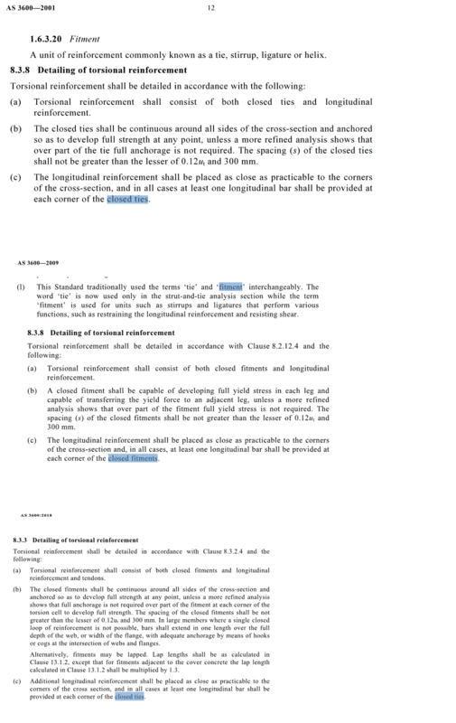
Edit: It would be interesting to know how (erroneous?) regression of the terminology occurs. In the image, a clause common to the 2001, 2009 & 2018 codes is shown. In 2001, 'tie' was acknowledged to be equivalent to 'fitment' and 'stirrup', and a closed tie meant the plain English version. In 2009, the code notes that 'tie' is trying to be used only in the strut & tie context, so is changed to fitment. In the 2018 version, 'tie' again refers to shear/torsion/restraint reinforcement albeit a very specific type, and there has for some reason been a switch back to 'closed tie' where it appears that 'closed fitment' is intended.

Closed_ties_zs8tyz.gif
 
Status
Not open for further replies.
Back
Top