Continue to Site

Eng-Tips is the largest engineering community on the Internet

Intelligent Work Forums for Engineering Professionals

  • Congratulations pierreick on being selected by the Eng-Tips community for having the most helpful posts in the forums last week. Way to Go!

ASCE 7 11.6 Rigid diaphragm

Status
Not open for further replies.

canwesteng

Structural
May 12, 2014
1,662
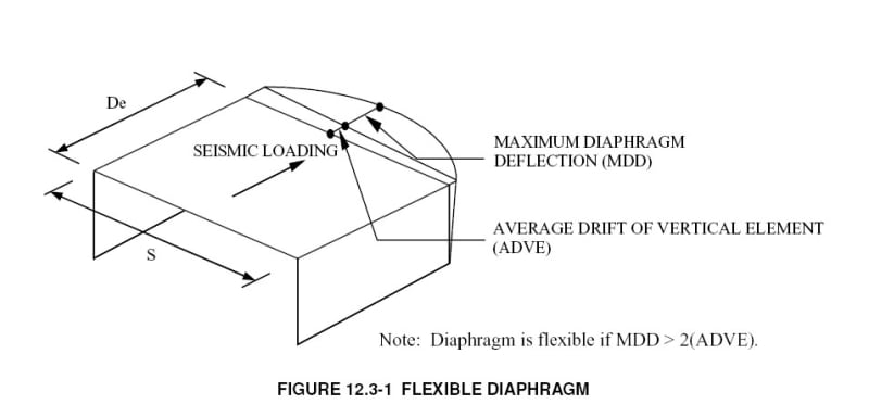
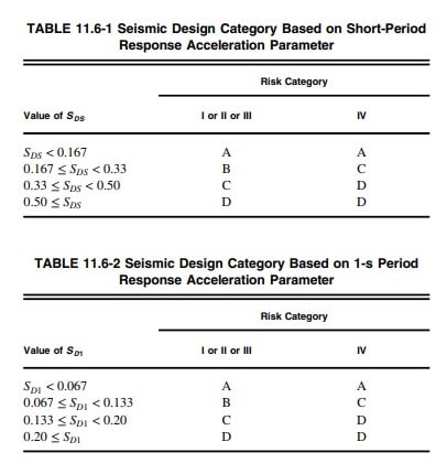
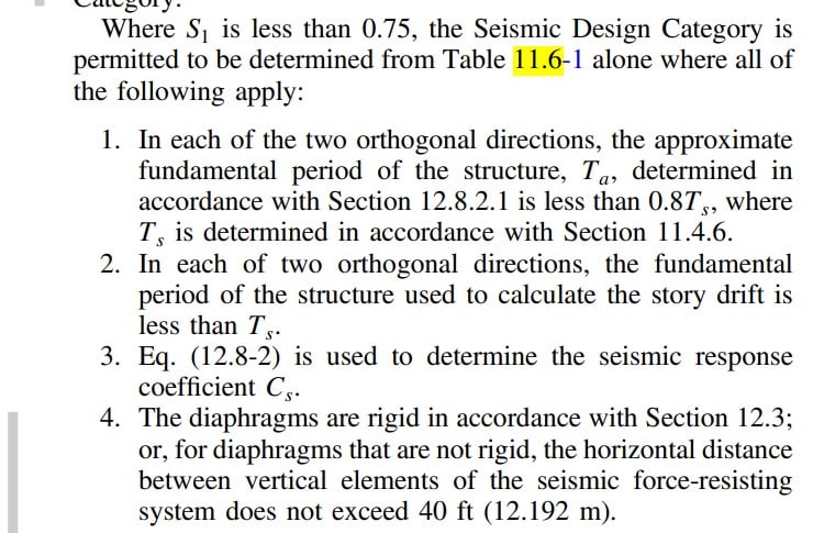
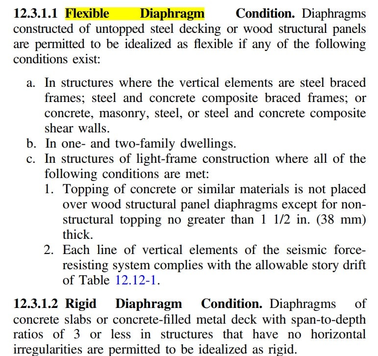
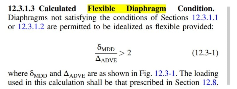
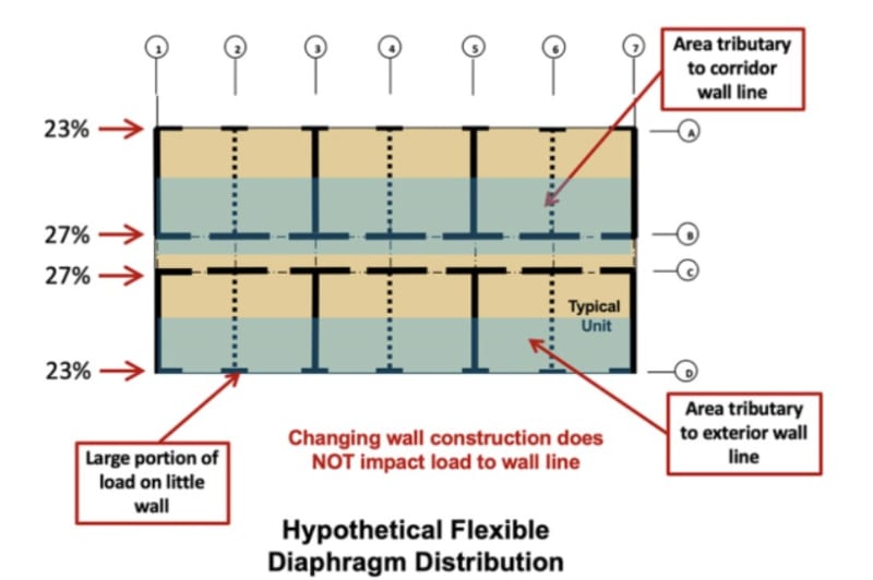
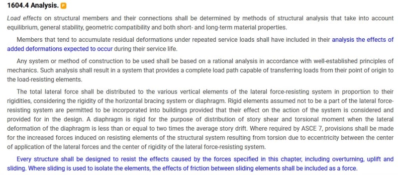
Section 11.6 allows us to use only table 11.6-1 to determine the SDC, which in my case lets me go to SDC C from D, which is pretty desirable. It points to 12.3 for the rigid diaphragm conditions, which seems to be only allow concrete deck to be called rigid. I'm wondering if there is any way justify calculating the actual stiffness of my diaphragm in order to call it rigid - I've come up empty handed so far.
 
Replies continue below

Recommended for you

What does your diaphragm consist of? Can you make an argument of a semi-rigid approach acting sufficiently stiff to provide justification for your intended situation? What does the commentary say?
 
If we are talking an untopped steel diaphragm they are pretty flexible and code permits them to be (blindly?) analyzed as flexible, if your moment or braced frame spacing is small enough, the diaphragm might calculate out as rigid.

Side note - the diaphragm deflection checks for rigid (by calculation) are performed at strength level forces, as I recall. If that helps or doesn't help, I don't know offhand. I think you need to either a) design quite a bit and iterate to "force" the systems (walls, frames, diaphragm) to satisfy rigid diaphragm analytically, or b) go with SDC D.
 
It's a braced diaphragm - I'm wondering how I can prove it will be rigid to satisfy the requirements of 12.3. It will be stiff enough to behave like one in this application, I just need to weasel out of SDC D (well I already have an out, which is to make the roof concrete, but I prefer not to do that).
 
I would go with Lex's suggestion, check your deflections, and rationalize rigidity that way. What's the system below that takes the load out of the diaphragm, is the distribution fairly uniform, or is the resisting system offset such that are areas of higher local stresses in the diaphragm?
 
It's a single story building, braced walls that are fairly tall with single bay bracing, vs the roof that I can fill with bracing. If you add any twist to it you can see it behaves as a rigid diaphragm, likewise if you were to knock out one vertical SFRS, it will still stand up with three sides braced. I just want some kind of backup that can rationalize this so I don't get caught having to change to SCBF later and the hours and tonnage just blow up.
 
Is designing for R=3 still an option? Or do you need to get into SDC C for that to be viable? I don't know those provisions that well.

You could potentially analyze it both ways and do the vertical elements for the worst case, but that doesn't sound like it's saving any design effort.

For a rigid diaphragm, there needs to be "enough" vertical support elements (the marriage of stiffness and spacing) to cause the wall/frame deflection to be similar to the deck deflection. If you're hung up on the diaphragm deflection, that's your metal deck, for factored loads, nothing fancy. You'd use the values from the SDI Diaphragm design manual or the manufacturer. I think a braced frame hurts you in this scenario because you are trying to get the horizontal deflection (of the frame) to get reasonably close to the diaphragm deflection).

Diaphragm_deflection_check_thd4wy.jpg

Image Source: Simpson Strongtie blog
 
R=3 for regular steel is not permitting for SDC D, and OCBF is only allowed for 45' tall warehouse buildings (I think a stretch to even use that in my case if I was even short enough). So I'm into an expensive system and want to squeeze into SDC C. There are some requirements that can be used to show you are flexible, because normally you want that, but if you don't meet those you are into semi rigid. I need something to lean on other than just my deflected shape, if such a requirement exists.
 
Yeah, run the diaphragm deflection calculations and check it versus the drift of the vertical LFRS. You didn't mention how tall your roof is yet.
 
It's ~60' tall, but that isn't really relevant. I would like to when I can call it rigid and not semi-rigid (which is what the check above is for, to determine flexible or semi flexible).
 
I've had mixed experiences with the deflection method personally, I decided to look at forces instead - if vertical elements take forces approximately in relation to their rigidity I consider the slab to be rigid. As far as I understand the point of it all, it's primarily to check if vertical elements are connected in a way that transfers larger force to a more rigid element.
I am not that familiar with US codes, Eurocode has a very similar provision, but as I said to me it seems more reasonable to check the distribution of forces.
I guess from the conversation that SDC is "seismic design class" and when I think about it I would expect rigidity of the diaphragm to be important because of the way forces are distributed - if one vertical element starts yielding it will become less rigid and more force will go to another element until all vertical elements yield. This would enable you to use up all of the available ductility (of course, if diaphragm remains elastic). If you have a flexible diaphragm rigidity of vertical elements has a smaller influence on force distribution which would mean that one vertical element can fail before others start yielding.
Am I missing something?
 
Well, nowhere in seismic design is anything intended to really remain elastic. There are areas that are specifically intended to deform and behave inelastically, but the elastic nature of the remaining structure isn't an explicit intent, if I recall correctly. There are sacrificial areas, if you would, where the damage is supposed to concentrate during a design seismic event and these are done to provide adequate energy dissipation via plastic deformation.

SDC is seismic design category, it varies based primarily on the Risk Category of the building and the two/three seismic acceleration parameters, SD1 and SDS and perhaps the long period one I forget the nomenclature for, TL.

When you have a lower SDC, (A, B, C), you have to option (in steel) of not detailing for seismic resistance, so you use an R=3, the other options use more detailing and reinforcing of the various elements and allow the use of larger R values.

R value is a divisor in determining the required resistances so the higher R value produces lower forces overall, but there are areas where the steel structure must be appropriately reinforced to preserve ductility under the required seismic forces, which can increase cost, sometimes more than if you designed for larger forces and R=3 and omitted the seismic ductility reinforcements of the various sections. For higher seismic design categories the R=3 option isn't allowed. (the table below shows H. as "NP" for Seismic Design Category D, "not permitted."

SDC_table_itx727.jpg


This also comes up in Steel Interchange, February 2018, Modern Steel Construction. There were a lot of articles earlier on the same subject, probably starting around 2000. And it's been discussed previously on this forum.
I've got an FAQ on the subject (now, created due to this question).

Normally design is required to be done for the more severe of the two seismic design categories determined from Table 11.6-1 (short period) and Table 11.6-2 ( 1 second period).

SDC_tables_tswfic.jpg


OP wants to wiggle into SDC C to avoid the detailing requirements, or I guess to permit R=3, which is possible in concept, provided all the correct seismic parameters cooperate.

Seismic_exception_7-16_uvgvzi.jpg

Source: ASCE 7-16

If you can't satisfy the requirements for the exception, then you need to design for Seismic Design Category D and provide the necessary detailing and reinforcement to the steel system.

Incidentally it's unclear which version of ASCE 7 we are discussing, but the discussion here is on the use of rigid diaphragm via computation.

To your question:
Hardbutmild said:
As far as I understand the point of it all, it's primarily to check if vertical elements are connected in a way that transfers larger force to a more rigid element.

Thematically, I suppose this is correct, or close enough, or it doesn't much matter "why", but I'll delve into the semantics a bit, if you're in the mood.

The check is to establish that the diaphragm is stiff enough to be reasonably accurate to model it as rigid, meaning that the stiffness of the diaphragm doesn't strongly influence the distribution of the lateral forces into the vertical seismic load resisting system ("moment or braced frames/shear walls") - so when you have a relatively stiff vertical system (braced frames, shear walls), that will help produce rigid diaphragm behaviour because the deflection of the vertical elements is lower than a moment frame.

EDIT - This isn't well worded. The check in question is to establish if a flexible diaphragm analysis is permitted.

It's the stiffness of the diaphragm relative to the vertical systems, so a stiffer (wall/braced frame) system means the diaphragm must be comparably stiff, a more flexible (wall/moment frame) system means the diaphragm must, again, be comparably stiff. The check is that the diaphragm deflects up to twice the average deflection of the (wall) system. If the diaphragm deflects "too much" (so to speak), relative to the vertical elements (wall), the diaphragm is permitted to be idealized as flexible. {meaning passing this check doesn't guarantee rigid diaphragm behaviour). This check doesn't prove rigid diaphragm behaviour is expected, it proves that flexible diaphragm analysis does or doesn't apply, so it's not quite the same thing, it's just something that's in the code, and if you don't satisfy it, you can't use a flexible diaphragm in the model.

If you do "fail" this check, it indicates that a flexible diaphragm condition doesn't really exist. As a side note, for this structure, we are presuming there are steel braced frames below, more or less, or rather, typically if there's a braced frame below the untopped steel deck, it would be permitted to analyze it as a flexible diaphragm per 12.3.1.1(a)


If the diaphragm is (strong enough) and stiff enough, the forces in the vertical elements will be distributed based on the relative rigidity of the vertical systems, so the one frame, if it is ten times stiffer than the other, it's going to take 10 times the lateral force, in a simplistic sense.

There are added wrinkles because you're required to add accidental torsion to increase the loads on the vertical elements, and apply the accidental torsion in both directions (up/down, left-right) and in both senses (+/-).

If you don't have a rigid diaphragm, the accidental torsion either doesn't appear or isn't required to be considered in the strength of the structure.

Louis Yaw has a paper on the analysis that's pretty digestible (how to do rigid diaphragm analysis).

With a flexible diaphragm, the forces are distributed based on tributary length, so if there are three vertical systems, the one in the center takes more force, but not due to the stiffness of the diaphragm, it's due to the larger tributary width (half the load, say, versus 25% on the ends), provided the middle one is in the center of the building.

OP has a steel deck, conventionally this is considered a flexible diaphragm, "untopped steel decking".

Flexible_diaphragm_definition_luhszc.jpg


Hardbutmild said:
If you have a flexible diaphragm rigidity of vertical elements has a smaller influence on force distribution which would mean that one vertical element can fail before others start yielding.

If you have a flexible diaphragm, the rigidity of the vertical elements has no effect on force distribution (this is a design simplification, so to speak, because all diaphragms have some rigidity). The sequence of failure of vertical elements isn't explicitly considered and there's no sequence of failure intended. If you design the structure appropriately, it's still expected to be damaged, during a design level event, and some of that damage will be due to design simplifications (i.e. force going where it's not intended but to an acceptable level that remains "acceptably safe").

There's two three ways to do this -
a) provide a concrete filled metal deck diaphragm. Which will be heavy and increase the lateral forces from seismic, perhaps influence the structure below due to added weight, including foundations.

b) add another frame so the 40' distance requirement is satisfied.

c) prove it does not satisfy calculated flexible diaphragm. (Maybe) I don't think the code really says "rigid diaphragm required" if you fail this check, but it stands to reason that the force distribution based on a rigid diaphragm (or semi-rigid, maybe) would be based on rational principles of mechanics and the alternative would be less accurate.

Classifying Wood-Sheathed Diaphragms as Flexible or Rigid, Woodworks, kind of backs up my reading of c) above. And it discusses the force distributions for flexible and rigid diaphragms in a reasonably clear fashion.

calculated_Flexible_diaphragm_ebacwj.jpg


In short, I think the OP is looking for a provision that doesn't actually exist in ASCE 7. It exists, just not in ASCE 7.
 
lexpatrie said:
so when you have a relatively stiff vertical system (braced frames, shear walls), that will help produce rigid diaphragm behaviour because the deflection of the vertical elements is lower than a moment frame.
This makes little sense to me. Imagine having two huge RC walls and connect them with something very flexible, like a rubber rope. Moving one wall would cause virtually no movement of the other wall. If you increase the stiffness of the walls nothing really changes, in fact the contrary is true... if you reduce two RC walls to be very slender rubber elements then maybe the rubber plate would act as a rigid diaphragm. Stiffer vertical system requires a stiffer slab to ensure the same level of rigid action. Consider for example old URM structures. They usually have 60 cm walls and decks made of timber (or wood, I don't know the difference... sorry), this is flexible, but the same slab is usually rigid enough if walls were made of wood.


lexpatrie said:
If you have a flexible diaphragm, the rigidity of the vertical elements has no effect on force distribution (this is a design simplification, so to speak, because all diaphragms have some rigidity).
I disagree. Imagine a plate supported on 10 vertical elements. Imagine one of them was a million times less rigid than the others. It's so flexible compared to other elements that it provides virtually no lateral support to the slab. Any statically indeterminate system requires you to know the stiffness of the supports to solve internal forces and support reactions, slab is no different than say deep beam in this respect.

I still think that OP could just model the whole thing, each element with its real stiffness and if the forces are close enough to the theoretically rigid solution then he could say that he can use SDC C. Again, I'm saying this because a few times I got that diaphragm is not rigid based on deflections, but forces were still basically distributed like in a system with a rigid diaphragm.
 
12.3.1 does say that you need to consider the diaphragm as semi rigid if it can't idealized as rigid or semi regid
 
Hardbutmild - I didn't word that first bit all that well, I've edited the previous post and stuck the revised text in italics, and struck out the cited portion. Does the revised language make more sense?

We are talking idealization here, so the physical analogies don't exactly apply, a rigid diaphragm is infinitely stiff in an analytical sense. No diaphragm is infinitely stiff, [similar to a "fixed" restraint for a foundation to a column in the old alignment charts, Gt or Gb = 0 is rarely achieved and Gb = 1 is recommended for a "properly designed footing", AISC 9th edition Steel Construction Manual, p.3-5.]

In this case the vertical elements take loads proportional to their relative stiffness, so the one side is 10x stiffer than the other, it takes 10/11ths of the load, the other side takes 1/11th. (Neglecting any accidental torsion requirements). With accidental torsion, BOTH elements will be designed to take more load, (because the accidental torsion is to be applied both sides of the center of rigidity). Louis Yaw shows that in his paper on the subject.

Hardbutmild said:
I disagree. Imagine a plate supported on 10 vertical elements. Imagine one of them was a million times less rigid than the others. It's so flexible compared to other elements that it provides virtually no lateral support to the slab. Any statically indeterminate system requires you to know the stiffness of the supports to solve internal forces and support reactions, slab is no different than say deep beam in this respect

The thing is, flexible diaphragm is statically determinate, or makes it statically determinate, so the whole argument fails. What you describe isn't a flexible diaphragm because the stiffness of the supports affects the forces they receive. In flexible diaphragm, forces are determined by tributary area/length. While it looks like a "deep beam" the beam in this case has only flexural resistance and no rotational resistance at any interior supports.

For a flexible diaphragm, no diaphragm is infinitely flexible. [ Similar to the old "10" for a pinned end of a column in the alignment charts, when it's technically infinity, AISC 9th edition Steel Construction Manual, p.3-5] In this case, the vertical elements take load based on their tributary lengths, so if they are at each end of the building, each takes 50% of the load.

Flexible_diaphragm_example_igqs2e.jpg

Source: Wood-Sheathed Diaphragms as Flexible or Rigid, Woodworks

The two extremes of modelling the behaviour produce reasonable results, within the confines of the limitations in ASCE/IBC.

Neither approach is guaranteed super accurate, and perhaps they arose more as something that was computationally convenient or achievable based on previous technology (slide rules, hand calculations, mini/micro/personal computers circa 1980s) and a lack of research. It is also likely that some of the semi-flexible diaphragms in a design level event will be damaged such that they stop being semi-flexible and become fully flexible, and that a rigid diaphragm gets damaged to the point of becoming semi-rigid (the semantic difference between semi-flexible and semi-rigid I'm not clear on). And the same could happen to the vertical system, for example with a wood shear wall it could get more and more damaged and become less and less rigid, causing the force to redistribute, potentially. It is known that the period of wood buildings will change during a seismic event.....

The "calculated flexible diaphragm" is a way of showing that the diaphragm acts reasonably close to flexible. If you don't satisfy the check a more detailed analysis is needed, but it doesn't technically make it a rigid diaphragm, however. I mention it because I think you have to disprove flexible diaphragm via calculation as part of proving it's a rigid diaphragm. Plus, the calculation is pretty straightforward and well-established.

When you are between rigid diaphragm and flexible diaphragm behaviour that's where we get into "standard of care" and an analysis that must be based on generally accepted principles of mechanics.

IBC_2018_1604.4_Analysis_hkk6rl.jpg


Code:
Any system or method of construction to be used shall be based on a rational analysis in accordance with
well-established principles of mechanics. Such analysis shall result in a system that
[u]provides a complete load path[/u] capable of transferring loads from their point of origin to the load-resisting elements.

(emphasis added)

Code:
The total lateral force shall be distributed to the various vertical elements
of the lateral force-resisting system in proportion to their rigidities,
considering the rigidity of the horizontal bracing system or diaphragm.

Hardbutmild said:
I still think that OP could just model the whole thing, each element with its real stiffness and if the forces are close enough to the theoretically rigid solution then he could say that he can use SDC C. Again, I'm saying this because a few times I got that diaphragm is not rigid based on deflections, but forces were still basically distributed like in a system with a rigid diaphragm.

I don't agree, but if you satisfy conditions 1, 2, and 3 in Section 11.6, above, and ADD vertical elements of the seismic force resisting system at 40' spacing maximum, you can actually satisfy the code and do it for SDC C.

If I were to go your route, (if it even panned out, we are talking about an untopped steel deck diaphragm in a fairly high seismic zone) I'd contact the relevant building official (and get sign off from the future owner), and see what they thought of it. That way, you aren't producing what could be viewed by the building official as a defective final design that violates code. Code review in what I suspect is California can be particularly precise.

I'll go out on a limb here and suspect that this is a non-snow region so the deck supports (Open web steel joists) are probably at 6' which will tend to make the deck more flexible as well.
 
I agree that wood diaphragms may act differently than concrete or steel because of specific detailing. I fail to see how in the case that you provide a horizontal steel truss or any system possible of acting like a continuous beam (versus a number of simply supported beams) this would not transfer forces based on stiffness, even if flexible. Relatively simple analysis could reveal force distribution.
Imagine 3 walls connected with a flexible slab. Each wall gets force according to its tributary area. Now change the middle wall material to pudding instead of concrete. The slab is still flexible, but only the outer walls get the force. You see, in the first case slab deforms with 2 "waves". This wave is large enough (2 times larger than wall deformation) to make it flexible. In the second case, the middle wall is basically air so you get a slab with a deformation that looks like one "wave". Still, it can be flexible if deformation is large, but forces are wildly different.

I definitely agree that you'd need to be careful, especially in a high seismicity area, but I do not like the idea of talking about some system being rigid and the other one not, although it is usually very useful. Make an untopped steel deck extremely thick (or add strong diagonals, we use different flooring systems in Europe) and you have a rigid diaphragm... it's all about the stiffness relationship.
 
If the middle wall isn't viable as a load path, you'd consider the diaphragm to span the full width of the building and then the end walls each taks 50% of the load (there's some eccentricity with wind loads if you have end zone pressures).

I agree it's the relative rigidity between the diaphragm and the "walls" but the diaphragms that tend to be rigid are particularly rigid, so the supporting vertical element stiffness doesn't influence it that much. That's the convention. How much of that is analytical convenience and how much is grounded in research and reality, that I don't know. I presume the two interact, and the evolving approach to "semi-rigid" diaphragm analysis is a natural seeming evolution in the process. If you deal with a moment framed concrete building, it seems quite likely that a rigid diaphragm won't produce drastically different results than some more detailed FEA version of the diaphragm....

Accidental torsion has it's own history, as well.
 
Status
Not open for further replies.

Part and Inventory Search

Sponsor