Continue to Site

Eng-Tips is the largest engineering community on the Internet

Intelligent Work Forums for Engineering Professionals

  • Congratulations cowski on being selected by the Eng-Tips community for having the most helpful posts in the forums last week. Way to Go!

ASME multi-leader lines and common datum feature

Status
Not open for further replies.

aniiben

Mechanical
May 9, 2017
158
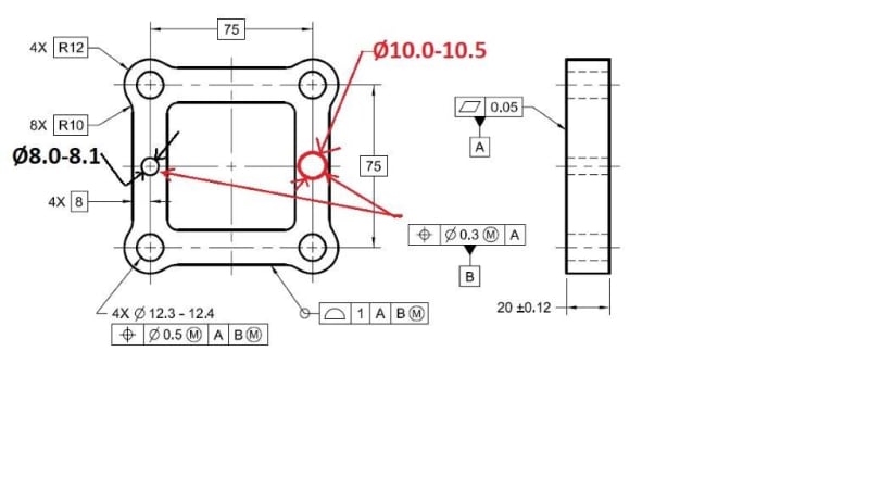
Sanity check: Are these two schemes valid in ASME?
Is they are kosher per Y14.5, then are they clear enough?


P1_-_Copy_q9py6k.jpg


P2_-_Copy_yxe2au.jpg
 
Replies continue below

Recommended for you

aniiben,

I think your top pattern is not kosher. You can use a hole pattern as a datum feature, but that is not a hole pattern. The ten millimetre hole can be datum feature[ ]B and the eight millimetre hole can be datum feature[ ]C. This looks like a modification of Figure[ ]4.39 in ASME Y14.5-2009. Note how that figure shows a pattern of eight millimetre holes.

Your second figure is the same thing. You have two separate features. They should be called up as two separate datums.

--
JHG
 
Multiple feature of size can be used as(Edited) a pattern per 2018 version section 10.5.3.4 Fig.10-52(or 2009 section 7.5.3.3 Fig. 7-51)

2020-06-02_112514_qjhyev.jpg
2020-06-02_112605_ajy64k.jpg
2020-06-02_112723_euurbq.jpg


Season
 
Multiple FOS can certainly be designated as a pattern. Multiple leader lines are not introduced in Y14.5 as a pattern creation mechanism (Y14.5-2009 para 1.3.42), if the intent is to treat it as a pattern it must be accompanied by or satisfy one of these methods. Season - in the figure you introduced, as well as in the text, the notation "nX" is utilized.

As far as whether a pattern can be designated together as a datum feature(s) - as long as its clear what is being referred to I think its fine even if they are of different size, though of course each feature could be designated individually as a datum feature and referenced as a multiple datum feature ie: |A-B|. For example a position tolerance accompanied by "nX COAXIAL HOLES" with a datum feature symbol attached would be clear. A single FCF with a datum feature symbol attached which is part of a simultaneous requirement with several other FCF, and expecting someone to interpret that the entire pattern held in SIM REQT is your datum feature would be far fetched and unclear.
 
In my figures the pattern of the holes or the pattern of two shown cylinders (bottom embedded figure) ARE datum features.
In the 2018 version (10-52) the pattern is not a datum feature.

What rules are not followed in my cases above?
 
aniiben,

Though it can be interpreted as to what you desire - namely that the two features with leader lines attached should be treated as part of a single pattern, it is strictly speaking not technically a pattern creation mechanism per the letter of the standard in Y14.5 as it does not utilize one of the accepted notations to designate a pattern (Y14.5-2009 para 1.3.42). Some may say as a result that your bottom case (two coxial diameters) is technically not a pattern. That said, I now realize in your top case the holes would be subject to simultaneous requirements and would be a pattern.
 
Chez311,
So are you saying that gasket picture (first figure) is per the standard's rule and can be interpreted, correct?
But the bottom figure (two coaxial cylinders) is not (per the rules and regulations).

Then, how can I change the second case to make it in agreement with the current Y14.5 technical rules?

 
I DO NOT think that any of the two schemes are correct. The pattern mechanism should have 2X and neither of them have it.
If they are not a pattern then, PROBABLY, you cannot make them a datum features neither on the first case or the second case.
So, datum feature B in the first OP's figure and datum feature A in the second OP's figure are NOT CORRECT. My reason: both of them do not have 2X!!!


I am expected a strong opposition to my statements and I will stand correctlycorrected if such evidence is provided.

 
greenimi,

You won't get strong opposition from me. I only said that while we can mostly interpret what the designer's intent is in both cases, the bottom one is certainly not a pattern per the letter of the standard. I initially said the top one was technically a pattern, but I am questioning that in light of pmarc's comments on a parallel thread as it is only a single tolerance. I typically considered multiple leaders to essentially denote "number of instances" so I considered them shorthand for separate tolerances, but I'm not sure that would be enough to definitively say simultaneous requirements would apply in this case.

Regardless, I would agree - both would benefit in clarity from addition of the 2X notation.
 
If 2X notation added on the 1st figure and followed the way of Fig 10-52, the two holes(with different size) will be a pattern, can we specify them as a datum feature? Edit: I will say yes in this case. Expect to see the valuable inputs from all VIP members, and I will stand corected.

Season
 
For the 2nd figure, the two coaxial features with a different diameter size, the multiple datum feature A-B will be more appropriate, this will be a slight different scenario from 1st figure, although they are all dealing with datum features.

What I focused is on the 1st figure, I think the OP's intent is: Can we use(or how to use) the multiple features with different size as a datum feature? Fig. 10-52 is just a method, we can treat them as a pattern just by adding a 2X notation, and then we can use the hole pattern as a datum feature. Please let me know if this logic is wrong.

Season
 
All,
I know a common datum feature A-B COULD be used, but my intent is to find
alternative ways and equivalent datum schemes to says the same thing (some people do not like or understand A-B common datum feature specially if you are using those as a datum feature.

 
SeasonLee said:
If 2X notation added on the 1st figure and followed the way of Fig 10-52, the two holes(with different size) will be a pattern, can we specify them as a datum feature?

Position tolerance FCF should be attached to a size dimension of a regular FOS * (the only case I remember from the 09' standard where a position tolerance is not associated with a size dimension is where it's combined with profile somewhere in chapter 8. It's for an irregular FOS, surface boundary control at MMC). So it can't be specified separately from both different size dimensions of the 2 intended holes. But if it is attached to one of the holes' size dimensions, I suppose "2X" needs to precede the already unusual position FCF (with the 2 leaders) but not the size dimension - which is also different from what's widely acceptable. Altogether this is not something I would support, definitely.

*Edit: except for coaxial features as in fig. 7-51 or the updated 2018 version of this figure posted here.
 
Indeed, I can't find out an application example in this way from the standards, the pattern idea failed. Would like to see the other ways to meet the OP's question.

Season
 
So, where do we stand here?
Do we agree that if 2X is added then OP's proposed solutions could be viable (should I say legal) even Y14.5 does not really show this approach with multi-leader lines?


axym said:
For example, the 2 coaxial cylinders in Fig. 7-59 have 2X a size tolerance, and a position tolerance applied to them. They are still treated as 2 distinct features - we would evaluate the size of each cylinder individually, and find the axis of each feature (not a combined axis).

Here is a quote from Evan, from a separate discussion, however I think relevant with the idea of common datum.
Question for the group:
Per Evan's input, what is datum A in the OP's second example? Is it the same as A-B case?
Otherwise stated if datum A is referenced as = A-B
and
datum B is referenced as A-B

are those two datum schemes equivalent with the OP's second case?

Again, based on Evan's input I do not think so.

Any other ideas?

 
I do not think the schemes shown by aniiben are in agreement with ASME, specially the second scheme.
Might be okay in ISO, but in ASME I doubt.


greenimi,

I'll need to read through this thread carefully before giving an opinion. I see that there has been discussion on leader lines and the lack of the 2X grouping mechanism in the 2nd scheme.

Evan Janeshewski

Axymetrix Quality Engineering Inc.
 
Axym said:
I'll need to read through this thread carefully before giving an opinion. I see that there has been discussion on leader lines and the lack of the 2X grouping mechanism in the 2nd scheme.

Evan,
Do you forget about this discussion. I am really interested in your valuable opinion.
 
Evan and all,

What will prevent us for attaching/ hang a datum feature symbol to the 2 COAXIAL CYLINDERS feature control frame?
If nothing, then maybe the OP's initial solutions are valid, don't they?

Any other opinions?


Gage_2003_-_Copy_qtgtts.jpg


Gage_2011_-_Copy_tnp4pm.jpg
 
Status
Not open for further replies.

Part and Inventory Search

Sponsor