Zach Lankton
Industrial
- Sep 28, 2018
- 6
Quick Question Regarding ASME Y14.5 2009 Section 7.53 Coaxial Pattern of Features of Size Question
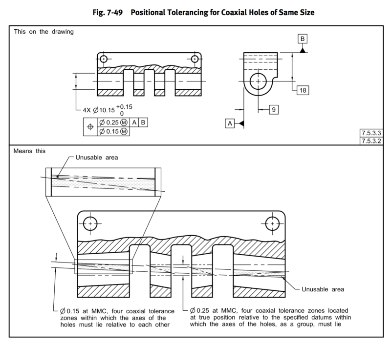
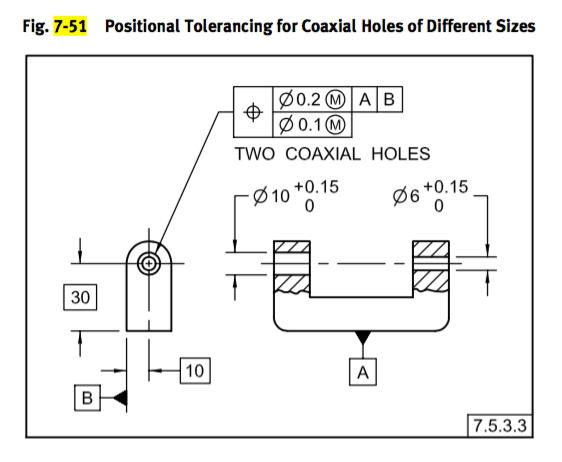
Ref Fig 7-49 & Fig 7-51
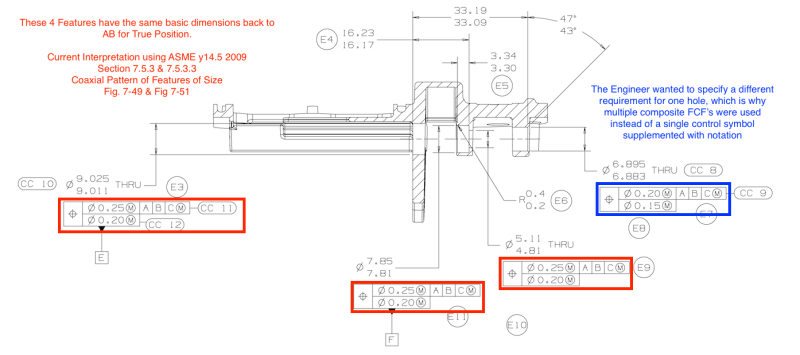
Attached is a photo of the drawing section that I am looking for opinions on.
There are 4 different size holes that are coaxial.
Section 7.5.3.3 Excerpt:
"...Where holes are of different specified sizes and the same requirements apply to all holes, a single feature control symbol, supplemented by a notation such as TWO COAXIAL HOLES is used. See Fig. 7-51. The same tolerance zone relationships apply as for Fig. 7-49."
This is well covered by Sec 7.5.3.3 & Figure 7-51 in the standard where requirements are the same for each hole.
However, in my case the requirement for one of the holes is different.
The engineer chose to use 4 composite FCF's. The intent seems clear to me that the lower segment should control coaxiality of all 4 holes, with one hole needing to be held to a tighter tolerance zone.
Figure 7-49 shows a single composite tolerance zone. My interpretation has been that the axis of the tolerance zone is established the same but the tolerance zone at this hole location is smaller.
So my question is...
Does the current drawing make this intention clear or am I totally wrong? If so, is there a better way to annotate this intention?
Thanks in advance!
Zach


