Continue to Site

Eng-Tips is the largest engineering community on the Internet

Intelligent Work Forums for Engineering Professionals

  • Congratulations cowski on being selected by the Eng-Tips community for having the most helpful posts in the forums last week. Way to Go!

ASME Y14.5 - 2018 Dynamic Profile Inspection 4

Status
Not open for further replies.

beakerj

Mechanical
Aug 31, 2021
4
To all my fellow GD&T enthusiasts out there... I'm curious, how are you inspecting dynamic profile from the ASME Y14.5-2018 standard if you are using it?

Example: How would you inspect, practically Fig 11-20, in the new standard? Assuming this is a CMM routine?
 
Replies continue below

Recommended for you

Would you not take as many points as the CMM routine required? That's the point of the Dynamic Profile symbol - to use a CMM.
 
Yes, I was assuming that they would take as many points as are needed. However, my question was more practically speaking, are there routines written in inspection software that handle this already? Seems like this would not necessarily be easy as a profile tolerance zone can take some very complex shapes.
 
Oh, you wonder if CMM makers are standards compliant in every way? I doubt that is the case.
 
beakerj,

I use an analysis software called SmartProfile, which supports dynamic profile.

The dynamic profile modifier allows the tolerance zone to offset (or "progress" as Y14.5 describes), so the CMM software needs to be able to apply that type of transformation. This is not particularly difficult from a computation point of view, but to my knowledge most CMM software packages don't include it yet.

Evan Janeshewski

Axymetrix Quality Engineering Inc.
 
KOTEM needs to update their page to include '2018.

EVOLVE SmartProfile allows you to define GD&T (GPS) tolerances according to the chosen standard (ASME Y14.5M – 1994, ASME Y14.5 – 2009, or ISO 1101). The built-in Explanatory System always shows relevant information from the current context.
 
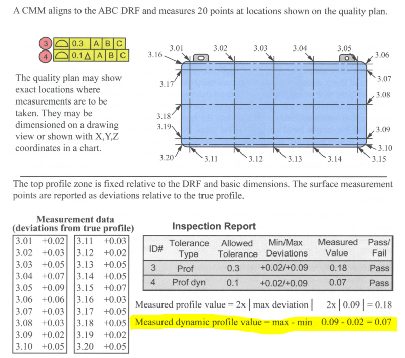
This is the first book that I have read till now dealing with dynamic profile CMM measuring and its report, here is a snapshot from "Goe Tol Pro 2020" page 11-35, I was surprised to learn that it was so simple : Dynamic prodile value = max - min (as highlighted).

2021-09-08_102433_yuhwko.png

Where datum feature A = bottom surface, datum feature B = right hole, datum deature C = the width of left hole

Season
 
That seems unlikely to be accurate in any but a contrived special case. For example - if the as-produced profile was slightly rotated it could show that the max-min = full profile tolerance >> dynamic profile tolerance even if the as-produced profile was exactly the same as the nominal profile except for that slight rotation.
 
Hi All,

The calculations in the book excerpt are correct. In one sense, dynamic profile really is that simple. The actual value (thickness of optimally progressed zone) is equivalent to the difference between the maximum and minimum deviations from the true profile (for well-behaved true profile geometry anyway). This is similar to the actual value of total runout being the total indicator movement (max indicator reading minus min indicator reading). Dynamic profile can be described as a generalization of total runout, that can be applied to general surfaces and does not require a datum axis.

I agree with 3DDave, however, that the book example is a special case. The actual value of dynamic profile is usually not as simple as a "max deviation minus min deviation" calculation. It's only this simple if the dynamic profile FCF has a fully constrained datum reference frame (which the book example does).

If we wanted to calculate the actual value of dynamic profile for the FCF's in Y14.5-2018 Fig. 11-35, 11-36, or 11-37, we couldn't just subtract the max and min deviations in the ABC DRF. There would also need to be optimization of the applicable rotations and translations (because these dynamic profile FCF's have partially constrained DRF's or are in the lower segment of a composite FCF). For Fig. 11-38 we could use the simple formula.

Evan Janeshewski

Axymetrix Quality Engineering Inc.
 
Ah yes; I had only seen the cases where either an orientation was left unconstrained. This one is a head scratcher for deciding when it would be used. The case for a revolved part could have been handled with a customized DRF, relieving the r coordinate of location control. Oh, wait. customization doesn't allow for cylindrical coordinate systems.
 
All very good input and helpful.
Thank you!
 
3DDave,

Dynamic profile should be used when the designer wishes to allow the "size" of the feature to float. If applied without datum features, as in Fig. 11-35, it becomes a general form control. If applied with datum features, it would control form along with whichever rotations and translations are constrained by the datum features (as in Fig. 11-37).

I agree that it's not possible to use a customized DRF to accomplish the same thing as dynamic profile (even for a revolved part). The radial coordinate in a cylindrical (or spherical) coordinate system is not considered an aspect of "location".

Evan Janeshewski

Axymetrix Quality Engineering Inc.
 
What example of a real part is there that allowing the size to "float" is necessary?

Y14.5 ignores cylindrical coordinate systems because CMM makers do not operate in cylindrical coordinate systems and their participation is critical to selling the standard. However, CMM makers can evaluate floating in size that cannot be done in any other way, making this a great sales tool. Use this feature and guarantee you have to pay for a CMM to check it.
 
The example I have heard of is a logo. You may want it's form controlled more tightly than it's location/size/orientation. I would welcome others to join in if they have seen other good candidates for the recommended use of it. I am exploring it's true practicality.
 
Examples: Gas tanks for different type of motorcycles.
 
A logo? First of all, a logo is controlled for scale - there isn't a uniform variation in a logo boundary that is acceptable. Second, the precision used in most graphics is very high as even slight misalignments will be unacceptable to casual visual inspection - it doesn't require a measurement to determine a print process has failed. If the screen you read this on had individual letters vertically misaligned by as much as 0.01 inch you would return the computer.

 
ASME Y14.5-2018 has also introduced a new Dynamic Profile Tolerance Modifier (a triangle symbol). The function of the dynamic profile is to allow form to be controlled independent of size. The example given was the gas tank on a motorcycle, it is fairly easy to understand the form needs to be precisely controlled but the size can vary much more without detriment to function.

Credit to Wes Cisco...part of his writeup....

"Here is the promised summary of the three GD&T focused sessions I attended at HxGN LIVE 2019:

ASME Standards Update and Overview of Y14.5-2018 - Fred Constantino @ASME & Rob Jensen @ Hexagon.
New GD&T Library for PC-DMIS v2019R2 and v2020R1 – Rob Jensen @ Hexagon.
Pc-Dmis Mathmatical Definition of Datum Features per ASME Y14.5 & Y14.5.1 - Dr. Daniel Wilcox @ Hexagon"

 
Cylindrity tolerance zone behaves no different than profile tolerance zone with the dynamic modifier.

Sphericity can be controlled with a profile tolerance with the dynamic modifier.

Any pair of features assembled together for which it is more important to control uniformity of the gap between them after assembly rather than the size of the gap can be controlled with a profile tolerance with the dynamic modifier.

 
What is the benefit suggested in the gas tank example?

The dynamic modifier is a uniform offset control so the part shape changes aspect ratio if it isn't a cylinder, sphere, or with multiple reflection or rotation symmetry as in a regular polygon for which a scale modifier would work just as well and be more universal.

For example - if a profile has a small radius, contracting normal to that curvature will eliminate that radius after progressing an amount equal to the nominal radius. Any other small feature can be eliminated in the same way.

However, scaling isn't so easy to manage for a CMM - the offset is not constant, so while it preserves both aspect ratio and all the contours, and would be applicable to logos, I can see why software makers would avoid advocating for it.

Scaling, by the way, is what molded/cast parts do as they shrink out of the mold, which dynamic profile doesn't describe.

Edit:
Hah - just noticed the presentations are from Hexagon. No surprise there.
Also, looking forward to a FEA where the uniformity of the gap is more important than the absolute size of the gap. If this has been a problem for a while it means that there has been a note on a drawing describing how to control that condition - there must be a published example for a shipping product that has a matching analysis for support.
 
Status
Not open for further replies.

Part and Inventory Search

Sponsor