Continue to Site

Eng-Tips is the largest engineering community on the Internet

Intelligent Work Forums for Engineering Professionals

  • Congratulations Danlap on being selected by the Eng-Tips community for having the most helpful posts in the forums last week. Way to Go!

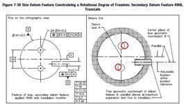
Fig 7-39/2018 question 1

greenimi

Mechanical
Nov 30, 2011
2,347
7-39 - Copy.jpg

In fig 7-39/ ASME Y14.5-2018

I think we all agree that the two bores should be “squiggly” (in the same way the outside diameter is shown a little “bumpy”), but my question is:
Do you think the correct way is to show the two (“squiggly” to be) holes slightly rotated clockwise? (my red adjustements)

I am comparing 7-38 with 7-39 and I am wondering why the holes in 7-39 are not rotated? Should they be? Shouldn’t they be?
Fig 7-38 looks okay, but if the intent is to show the same part on both scenarios (with and without the translation modifier) then why 7-39 does not show rotated holes?
 
Replies continue below

Recommended for you

The hole may not and will not exactly be round so the nominal sides may not be the actual sides.

If the tertiary hole is referenced RMB, then the simulator pin needs to be expandable (at least in theory).

By "entire hole" I mean that I don't want two predetermined points/lines on the hole to constrain clocking. These may be other points (yes, probably close to the hole sides, but not necessarily the ones at exactly 3 and 9 o'clock).
 
None of that affects how the assembly uses that feature, it's a CMM game that produces solutions that evaporate on the factory floor.
 
I assume you noticed that pretty much same conclusion (regarding the effect of the usage of the translation modifier on the hole) was formulated by Burunduk and confirmed by me about 20 replies ago in this thread.
 

Part and Inventory Search

Sponsor