Continue to Site

Eng-Tips is the largest engineering community on the Internet

Intelligent Work Forums for Engineering Professionals

  • Congratulations Danlap on being selected by the Eng-Tips community for having the most helpful posts in the forums last week. Way to Go!

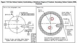
Fig 7-39/2018 question 1

greenimi

Mechanical
Nov 30, 2011
2,347
7-39 - Copy.jpg

In fig 7-39/ ASME Y14.5-2018

I think we all agree that the two bores should be “squiggly” (in the same way the outside diameter is shown a little “bumpy”), but my question is:
Do you think the correct way is to show the two (“squiggly” to be) holes slightly rotated clockwise? (my red adjustements)

I am comparing 7-38 with 7-39 and I am wondering why the holes in 7-39 are not rotated? Should they be? Shouldn’t they be?
Fig 7-38 looks okay, but if the intent is to show the same part on both scenarios (with and without the translation modifier) then why 7-39 does not show rotated holes?
 
Replies continue below

Recommended for you

greenimi,
Burunduk said that only one of your statements was true. In my opinion, both are true (if we take them as general statements).

So if both of my statements are true

- There are “as produced” holes that meet translation modifier DRF |A|B|C TRM|, but do not meet |A|B|C|
- There are “as made” holes that do not meet |A|B|C TRM| DRF, but meet |A|B|C| DRF.


then there is NO one DRF more "powerful" than the other
or
NO one DRF creates a more stringent requirements than the other DRF.

Initially I was even thinking that the movable DRF is more “like a subset” of the fixed DRF, but looks like that is not the case.

Do you see what I mean? Or maybe now I even confused myself :)
 
The translation modifier does not cancel the default requirement for the tertiary datum feature simulator at RMB to be a set of two parallel planes at maximum separation.
That is a good point that I missed.
So I agree with you that in this and similar cases, the translation modifier doesn’t necessarily make acceptance easier—it just changes the requirement.
 
Burunduk,
I am not disagreeing with you, just asking an innocent question:
Are you still agreeing with your own statement below
Considering the image pmarc posted above, from 2 years ago from this discussion or you changed your mind?


"If the key component which fits in the groove in the assembly this part is used at is fixed/constrained relative to the center axis of the bore in which datum feature A mates, then the option without the translation modifier is preferable, and it is more restrictive.
If the key is inserted into the groove manually without constraints, then the translation modifier can be used, and this option is more permissive, because more variation is allowed for the orientation of the 2 holes.
Note that the order and nature of constraints of degrees of freedom are identical in both cases, therefore the modifier cannot be substituted by other tools such a customized DRF for its purpose."


the translation modifier doesn’t necessarily make acceptance easier

I am asking in comparison with the statement you made in this thread.
So, "doesn’t necessarily make acceptance easier" versus " it is more restrictive" / " this option is more permisive"
 
Last edited:
"doesn’t necessarily make acceptance easier" Is the correct statement.

Also i stand by the one I made earlier in this thread: "However, it is not so in all cases and I don't think it was the "design intent" of the translation modifier idea to allow additional variation. In another use of this modifier, 7-12 in Y14.5-2018, it doesn't add any leeway, or if it does it is neglectable. Instead it allows fuller and more reliable interface between the datum feature and the adjustable (RMB) datum feature simulator."

You live and learn.
 
Burunduk,
The intent behind the introduction of the translation modifier in the 2009 standard was... well, to have a way to define what used to be the default condition in the 1994 standard (except for the cases where, for some unknown reasons to me, it wasn't ;-]).

The consequence of that is a different interaction between the datum feature simulator and the datum feature itself. In some cases, this may result in a quite different part-to-DRF relationship (Fig. 7-38 vs. 7-39), in some cases the difference may not be that clear and impactful (Fig. 7-6 vs. 7-12). But the difference is inherently there.

In other words, saying that "it allows fuller and more reliable interface between the datum feature and the adjustable (RMB) datum feature simulator." is true, but does not come without a consequence.
 
The intent behind the introduction of the translation modifier in the 2009 standard was... well, to have a way to define what used to be the default condition in the 1994 standard (except for the cases where, for some unknown reasons to me, it wasn't ;-]).

I think it wasn't "default" as much as "undefined." The CMM operators took it one way, the engineers took it a different way. On designs where the "tertiary" effect of a second hole was solely alignment we used two, orthogonal tolerances to show that the only one direction was to be used as a datum feature. The problem with the math was never addressed by metal.

The translation symbol merely hid this and made a slightly different mess of it. For our case we used a diamond pin to remove the radial variation constraint on an MMC tertiary.

I have never seen an assembly with an expanding pin to fully engage the hole that allowed freely sliding motion translation and rigid clocking that the current translation modifier represents, but I do know how convenient that interpretation is for CMM software and operators.
 
We can call it "undefined", if you prefer, even though para. 4.5.3(d) seemed to provide the default. Unfortunately, in the figure referenced in that paragraph (fig. 4-15), they showed the tertiary TGC of C not only oriented to the TGCs of A and B, but also located ("aligned") to the TGC of B, which was against their own rule.
 
That's where I don't see the connection - which rule? It appears to describe a condition where the tertiary simulator is fixed in location and expands.
 
The rule in 4.5.3(d) says the tertiary simulator must merely be oriented to the primary and secondary datums. Fig. 4-15, however, shows something different.
 
"may be aligned" is what Fig. 4-15 shows. What it doesn't say and where the ambiguity lies is that the location of the tertiary feature is allowed to move. It only refers to the orientation of the contacting surfaces.

I have yet to see an assembly that necessarily behaves the way that 2009+ allows.
 
"May be aligned" in the text refers to the datum feature in nominal condition, not to the TGC of the datum feature - at least that's how I read it.

The figure shows the TGC of C aligned with datum axis B, which is possible only if the tertiary datum slot has zero location error relative to A|B. It's a confusing example to say the least.
 
It doesn't just show it - there is a clear statement that the alignment is part of the interpretation.

In the absence of realizable and necessary mechanism, I don't see that such movement would ever be assumed.

The problem is that in the case of a slot it can force alignment all by itself, but if the tertiary is a circular hole or pin it cannot. The assumption is the pin doesn't change in clocking but the slot does. This is ambiguous and best resolved by having neither feature change in clocking.

If the tertiary mate is a spring clip, it would need to be on a 4 bar parallelogram mechanism to allow movement without allowing rotation or move in a dovetail slot, but neither would allow easy access to the full depth of the slot, so a double mechanism or a double slot mechanism would be needed, the way a cross slide functions. but without the restraint on location that a cross-slide provides.

I'm not concerned with "possible." I am only interested in "necessary."
 
The tertiary hole could be there to enable spot welding and as such could have pretty generous position tolerance relative to A|B. But forcing the tertiary simulator to stay at basic location from datum axis B wouldn't make much sense.
 
The tertiary hole could be there to enable spot welding and as such could have pretty generous position tolerance relative to A|B. But forcing the tertiary simulator to stay at basic location from datum axis B wouldn't make much sense.
I agree with your assessment.
But "they"-ASME- have to chose a default condition and that default is "basic orientation AND basic location". If the designer does not want that then the designer can intentionally use translation modifier. (same idea for the RFS default condition)
Looks like ISO (based on your input pmarc) will follow ASME footsteps in the near future and will change the default condition to basic orientation and basic location. Am I correct?

Therefore, maybe the translation modifier is severely underused. (maybe a solution looking for a problem)
 
greenimi,
In the newest version of the ISO standard for datums, ISO 5459:2024, they have not changed their default to basic orientation and location - it is still basic orientation only.
 
The tertiary hole could be there to enable spot welding and as such could have pretty generous position tolerance relative to A|B. But forcing the tertiary simulator to stay at basic location from datum axis B wouldn't make much sense.
That's why a rectangular zone would be used and only the component that directly controls rotation used as a datum feature.

Let's say that it is for spot welding. That's in a fixture. Where should the pin in the fixture be if the diameter 0.250 inch tertiary hole can be +/-5 inches from the axis? Won't that hole/slot be punched in a progressive die for mass manufacture or laser cut for limited production? Maybe a tighter control or using a slot?
 
In the newest version of the ISO standard for datums, ISO 5459:2024, they have not changed their default to basic orientation and location - it is still basic orientation only

pmarc,
And based on YOUR (widely known) knowledge of both systems, do YOU think that is a good thing or not

Or

ISO is more wisely than ASME (I mean they, the ISO guys, learned the lesson from the ASME implementation or lack thereof)?
 
Last edited:
3DDave,
I don't understand what component of a tertiary hole for a spot weld directly controls rotation. It's the hole, as a feature, that controls rotation (clocking). Regardless of how far the actual hole is from the secondary datum axis (within acceptable tolerance), I want the entire hole to be used as a feature that will stop the last remaining rotational DOF of the part.

I don't want to use a diamond pin simulator basically located relative to the secondary datum axis for that, because the actual distance deviation of the tertiary hole may be so big (yet within the position tolerance) that the diamond pin may not even be able to fit inside the hole. Unless you design it such that it can translate from-to the secondary datum axis.

The manufacturing method has little to do here, in my opinion.
 
And based on YOUR (widely known) knowledge of both systems, do YOU think that is a good thing or not

Or

ISO is more wisely than ASME (I mean they, the ISO guys, learned the lesson from the ASME implementation or lack thereof)?
I don't have an opinion here and, to be honest, it is a difficult question to answer. It's like asking whether it is good or not that Rule #1 is the default. Ask two persons and you will get three opinions.
 
3DDave,
I don't understand what component of a tertiary hole for a spot weld directly controls rotation. It's the hole, as a feature, that controls rotation (clocking). Regardless of how far the actual hole is from the secondary datum axis (within acceptable tolerance), I want the entire hole to be used as a feature that will stop the last remaining rotational DOF of the part.

I don't want to use a diamond pin simulator basically located relative to the secondary datum axis for that, because the actual distance deviation of the tertiary hole may be so big (yet within the position tolerance) that the diamond pin may not even be able to fit inside the hole. Unless you design it such that it can translate from-to the secondary datum axis.

The manufacturing method has little to do here, in my opinion.
Only the sides of the hole matter. A slot would work the same.

So the +/- 5 inch motion will be handled how exactly? What if it is 6 inches? Is that acceptable also? 10 inches? 100 inches? There must be some manufacturing limitation.

The diamond pin will fit because the tolerance applied will allow it to fit and not require a complicated mechanism.

Why the entire hole? I can guess. It's on a CMM and it is difficult to determine exactly where the diametrically opposing points on the hole are, but with 3 points at about 120º spacing one can determine that center. You don't need the entire hole in the real part or on a real fixture; you only need it on a CMM, which doesn't care about the radial distance, unlike the jigs and fixtures in manufacturing.
 

Part and Inventory Search

Sponsor