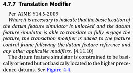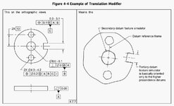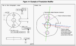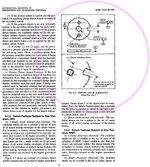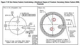
In fig 7-39/ ASME Y14.5-2018
I think we all agree that the two bores should be “squiggly” (in the same way the outside diameter is shown a little “bumpy”), but my question is:
Do you think the correct way is to show the two (“squiggly” to be) holes slightly rotated clockwise? (my red adjustements)
I am comparing 7-38 with 7-39 and I am wondering why the holes in 7-39 are not rotated? Should they be? Shouldn’t they be?
Fig 7-38 looks okay, but if the intent is to show the same part on both scenarios (with and without the translation modifier) then why 7-39 does not show rotated holes?

