Eng-Tips is the largest engineering community on the Internet

Intelligent Work Forums for Engineering Professionals

At what pressure do I get full flow? 6

Status
Not open for further replies.

PNachtwey

Electrical
Oct 9, 2004
772
0
0
US
Backgound,
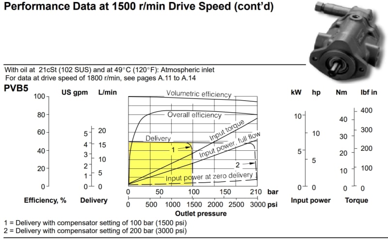
I have a small eaton-vickers pump that looks almost like this only mine is green.
It has a 5 HP motor driving a 5 gpm pump at full flow.
We no problems with setting the system pressure at about 1500 psi when there is no flow. We can't adjust it much higher because the 5HP motor is limited.
The pump should provide no flow at 1500 psi.
The question I have is at what pressure do I get full flow?
It seems to me this is a function of the spring. Adjust the spring in and out adjust a proportional band where the flow is proportional to the pressure drop from 1500 psi. However, there is no way to know how far the pressure must drop to get the full 5 gpm from the pump. It seems to me that this would be a function of the spring constant. A stiffer spring would more cause the port to the swash plate to open up more with a smaller pressure drop. This essentially is changing the proportional band of the pump.

Are there specifications for this?
Are there specifications for how fast the swash plate moves?
Is it possible to replace the spring in the compensator?
As a controls person this seems simple but crude.
BTW, know the flow because I can measure the speed of the piston and know the areas of the piston but I am looking for a general case.


Peter Nachtwey
Delta Computer Systems
 
Replies continue below

Recommended for you

I agree with hydtools, as long there is enough power in the prime mover the pump should deliver max flow up to pressure cut off. (the diagram shows a rounded corner though)
Here is a Vickers pump with specs that look more like the one on the video, with only a max pressure compensator for max pressure stand-by. Hydtools pump also had a low-pressure stand-by compensator, but the principle will be the same.
So this pump thrives to maintain compensator pressure setting till swashplate has reached its max angle. If you ask for more flow at that position it will result in an instant pressure drop. So the flow has to be controlled with a directional valve variable orifice and of course the load pressure downstream the orifice. On the detailed schematic, it seems like the bias spring is "adjustable" or replaceable for other pressure ranges(??).
PVB5_Vickers_csk5st.jpg
 
According to the catalog specs the pump delivers full flow at all pressures less than the compensator setting. That has been my experience, too.
This can't be so. The pump can't go instantly full stroke when it drops one psi below the pressure set point. This would cause an unstable response.
I am looking at the details.
My pump is probably the PVM018 on page 12. We bought the HPU used off of e-bay and didn't get documentation. Now I have some I think.

It looks to me like the pressure change A is 40 psi so if I have the compensator set for 1500 psi then I get no flow at 1500 psi but at 1500-40 psi I get close to 100% flow minus the droop of up to 1.2 gpm.
It looks like the pump flow vs pressure goes up the right side of that pump curve and it looks linear. In my case it looks like if the pressure drops 20 psi to 1480 I will get the rated flow minus a little for the droop and and divided by 2. Basically the pump performance is going up and down the right side of the pump curve.

I don't think akkamaan's graph has the detail I need.

What is interesting is that some pumps will have a pressure drop of 40 psi and other have a drop of 150 psi before they are on full stroke but the line look linear going up to the left.

Thanks hydtools for the document. I am not quite sure which pump I have because I am self isolated at home but I think I can find out tomorrow.

What is also interesting to me is the standard response times at the bottom of page 8. Some are very long and others like the PVM018 are fairly decent. It would have been nice to see the swash plate vs time curves. I need to stick that into my simulator. I have always assumed the pump responses were more like the 150 ms.


Peter Nachtwey
Delta Computer Systems
 
Their 8.5 GPM for the PVM018 (chart at bottom of page 12) is based on 1800 RPM. Your motor will be operating at less than that, ~1750 RPM depending on your actual motor.

Q absolute max = RPM x cc x 100% / 3780. At 1750 RPM, Q absolute max = 8.33 GPM.

If you have the Industrial (not Mobile) PVM018 (pg 12) and your compensator setting is 1500 psi, then with the 1.2 GPM "droop", you will have 8.33 GPM - 1.2 GPM = 7.13 GPM @ 1460 psi, and 7.13 / 2 = 3.56 GPM @ 1480 psi.

You originally asked "The question I have is at what pressure do I get full flow?" If by full flow you mean the absolute max flow this pump could put out, you will only get this flow at 0 discharge psi, meaning pump is just putting out free flow, like dumping fluid out of its discharge directly into a bucket. As soon as pressures begin to climb, volumetric efficiency begins to reduce. For some pumps, it can go down below 90%. For most pumps, it's in the 90% to 96% range at the higher pressures. This is all based on no test experience, just looking at mfr performance curves.
 
I know about motor slippage.
What I didn't know is how far the pressure must drop before the swash plate was fully tilted and providing full flow. I was wondering about the slope on the right side of the pump curve. Apparently there is a lot of difference depending on the model. I can see there is no standard even within the same company or series of pumps. This needs to be another parameter in my pump model.

If you have the Industrial (not Mobile) PVM018 (pg 12) and your compensator setting is 1500 psi, then with the 1.2 GPM "droop", you will have 8.33 GPM - 1.2 GPM = 7.13 GPM @ 1460 psi, and 7.13 / 2 = 3.56 GPM @ 1480 psi.
Yes. This means that the variable displacement pump must be sized a little larger than what would be required for a fixed displacement pump.

If I have a VFD driving a fixed displacement pump I think that would be optimal. The motor and drive would be more expensive but the pump itself would be cheaper.


Peter Nachtwey
Delta Computer Systems
 
This means that the variable displacement pump must be sized a little larger than what would be required for a fixed displacement pump.

Instead of a larger size pump, just set the compensator setting higher. If you need up to 1500 psi with max swashplate angle, just set the compensator at 1600 or 1700 psi. That sounds too obvious and I know you are aware of that. I guess I'm not fully understanding the issue at hand for you. If you're trying to program something, then yeah it varies by pump brand, series, and even by displacement size within a series. Just have to read the charts, graphs, and data, and get the calculations going. Tedious process for sure.
 
Yes, I am trying to simulate a hydraulic servo system. I need to keep the pressure as constant as possible. The pump I have seems to be fully on stroke with just a 40 PSI drop. That is good. Having the pump come on stroke with 200 psi drop is not. This affects the accumulator size if I want to minimize the pressure drop. I am taking into account the motion profile so instantaneous demands can be calculated. This is the easy part since I have done this before. My pump models have been kind of crude. Now I want to simulate the curve using the A and B parameters in the document that hyd_tools provided. I also need to determine the operating point on the curve as pressure changes and also the response of the pump since the swash plate doesn't move instantly.

I am going to use this information in my next H&P article. I have a python program written that sizes cylinder diameter, rod diameter, valve size and accumulator size. It outputs a graph of the motion profile, the instantaneous flow requirements. How much the volume of oil or gas in the accumulator is changing, the system pressure and the gas volume in the accumulator. For the small cylinder size I use standard sizes but for the larger sizes there are no standards so the user must override the programs calculation with the next available size. The program will recalculate the results but not override the users input.


Peter Nachtwey
Delta Computer Systems
 
HydraulicsGuy said
If you have the Industrial (not Mobile) PVM018 (pg 12) and your compensator setting is 1500 psi, then with the 1.2 GPM "droop", you will have 8.33 GPM - 1.2 GPM = 7.13 GPM @ 1460 psi, and 7.13 / 2 = 3.56 GPM @ 1480 psi.
I have a simulation and equations but I get a different answer from you. The difference is due to the flow droop. You are there will be 1.2 GPM droop at 1500 psi. Doesn't the flow droop apply to the maximum pressure? I don't see when the flow drop would be a constant and that severe if I changed my pressure set point to 1200, 1500, 1800 psi.

Hydtool's pdf file is a great help.

However, now my HPU simulator just got more complicated because there are new parameters.
Ton and Toff, are on stroke and off stroke times. I use these to simulate the pump swash plate doesn't move instantly.
Qdroop and Pdroop for the flow and pressure droops. I am assuming these droops occur over the maximum flow for the Qdroop but the Pdroop is a difference between the set point pressure at 0 flow and the set point pressure - Pdroop for the full flow.

I have a formula now
Q(p)=max(min(Qmax-Qdroop*p/Pmax, Qmax(Pset-p)/Pdroop),0)
I then run that through a low pass filter to simulate the response time of the swash plate as it changes stroke.


Peter Nachtwey
Delta Computer Systems
 
You are there will be 1.2 GPM droop at 1500 psi. Doesn't the flow droop apply to the maximum pressure? I don't see when the flow drop would be a constant and that severe if I changed my pressure set point to 1200, 1500, 1800 psi.

I agree with you. Apologies there. I was assuming that the "A" and "B" values on that graph on pg 12 applied to all compensator settings, but after looking more closely, I believe they apply to only the 315 bar (4568 psi) compensator setting. Trying to answer questions here and do the work at home thing with family around doesn't always work out well.

The only thing is, the "B" value on pg 12 is not in-line with the "Delivery and Efficiency" graph on pg 18. According to that graph on pg 18, the volumetric efficiency (Ev) never drops below 96%, even at 4500 psi. Flows would be:

Q = RPM x cc x Ev% / 3780
Q = 1750 x 18 x 100% / 3780 = 8.33 GPM @ 100%
Q = 1750 x 18 x 96% / 3780 = 8.00 GPM @ 96%

This is a "droop" of only 0.33 GPM, not the 1.2 GPM given on pg 12. I'm not sure how to rectify this. I guess you rectify it by saying the 1.2 GPM droop (from 0 psi to 4500 psi) applies when you have the pressure compensator control on the pump. When you don't have any pump controls on the pump, then the 0.33 GPM droop (from 0 psi to 4500 psi) applies.
 
Hydtools, another issue. You assume the slippage is 50 RPM. That is a good estimate for a motor like I have at full load. However, when the swash plate is neutral there is little or no load but friction. The slip will be smaller. I wonder if slippage is taken into account with the volumetric efficiency. I am look into your point about the droop.

Peter Nachtwey
Delta Computer Systems
 
when the swash plate is neutral there is little or no load but friction.

We tested an HPU a few months ago. We measured current with the swash plate neutral, pump in pressure-compensated state. For reference, full load amps was 57 per motor datasheet. Measured amps was 25. I had found a US Dept of Energy document that had some generic curves for Efficiency and Power Factor when at much less than full load. Using approximate Efficiency and Power Factor from that document, and applying the motor equation P = V x A x Eff x PF x 1.73, I calculated that the motor was still outputting 15 HP. It was spinning at say 1750 RPM, so:

T = 15 HP x 63000 / 1750 RPM = 540 lb-in.

Full load torque per motor datasheet was 148 lb-ft = 1776 lb-in.

So in the pressure-compensated state, the motor was still needing to generate a good amount of torque, ~30% of its full load torque per my calculation.

Another way to calculate it, simpler but probably not as accurate: 25 Amps / 57 Amps = 44% of full load torque.

The slip will be smaller.

I agree. So you can interpolate between 1750 RPM and 1800 RPM for say 30% or 44% of full load torque (if you want to use my numbers above).

I wonder if slippage is taken into account with the volumetric efficiency.

Speculating that they probably measure the RPM of the pump shaft or the motor shaft with a tachometer or other device, measure the pump output flow and pressure, and calculate the volumetric efficiency for the different pressures. So they're basically saying, 'if this is your pump discharge pressure, this is your volumetric efficiency, regardless of what speed the motor is at'. I hope that makes sense. I don't see them trying to calculate motor slippage and then using that for their input RPMs.
 
I want to add that other pump manufacturers actually publish motor power required in the pressure-compensated state. Using that power figure and speed, you can calculate torque and compare to the full load torque to see where you are speed-wise. From one of the pump mfr graphs that I saw, the power was quite a bit less than the 15 HP that I calculated for the pump we had, for a comparable size pump. I want to say it was like 5 HP, so a lot less torque, therefore much closer to the synchronous speed of 1800 RPM. If you want me to point you to where I saw this in one pump mfrs catalog, let me know.
 
When using engines, yes. I want the engine to approach its peak torque as the load causes the engine speed to decrease. So I am interested in the torque curve.

Ted
 
Status
Not open for further replies.
Back
Top