Continue to Site

Eng-Tips is the largest engineering community on the Internet

Intelligent Work Forums for Engineering Professionals

  • Congratulations GregLocock on being selected by the Eng-Tips community for having the most helpful posts in the forums last week. Way to Go!

Axial Flow pump - Flow / BHP 1

Status
Not open for further replies.

tuneball

Mining
Jul 4, 2015
14
Hello,

Can someone please explain why BHP decreases as flow increases on a Axial Flow pump curve.


Thanks
 
Replies continue below

Recommended for you

No simple explanation. Has to do with the impeller/propeller design characteristics determining flow paths though the pump. These can be generally indexed using the Specific Speed of the design. Axial flow pumps have Ns (Specific Speed) in the 9000 and above range, and as the flow becomes more radially directed from the shaft, the Ns becomes lower.

I'm afraid that's as deeply as I can explain it; basically impeller design determines the shape of the performance curve and rising HP with lowering flow is a characteristic of the axial flow design.

One of the pump design experts we have frequenting this forum could give a much more detailed answer, but you might have to get pretty deep into pump hydraulics to fully answer your question.
 
If you care to calculate the power required at any flow / head point on the HQ curve of an axial flow pump it is self explanatory.
hp=gpmxft/3300/eff (imp.gallons) or
kW=l/sxm/102/eff ( metric terms).

It is a capital mistake to theorise before one has data. Insensibly one begins to twist facts to suit theories, instead of theories to suit facts. (Sherlock Holmes - A Scandal in Bohemia.)
 
look at the following info. on pump specific speed, I haven't reviewed it completely however it appears to answer your question plus more.

It is a capital mistake to theorise before one has data. Insensibly one begins to twist facts to suit theories, instead of theories to suit facts. (Sherlock Holmes - A Scandal in Bohemia.)
 
This helps a lot, thanks guys, much appreciated!
 
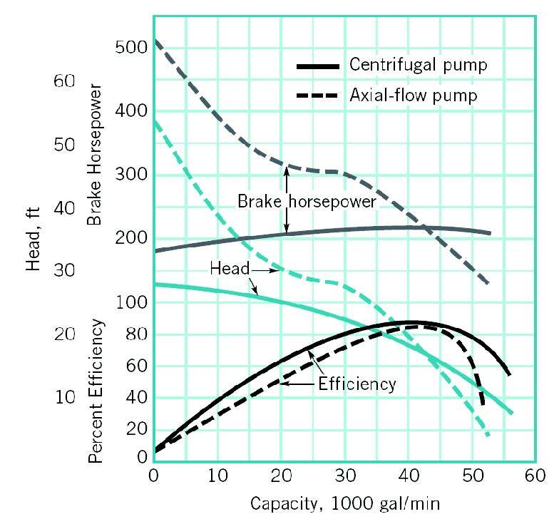
Axial flow pumps have performance characteristics that differ drastically from other centrifugal pumps. Although axial flow pumps produce very low heads at their normal operating point, the curve of head to capacity ratio is much steeper than other pump types. The shutoff head can be up to three times the head at the pump’s ,maximum efficiency point The HP required increases as flow is decreased with the highest HP draw being at shut off. This is because of the significant change in head with pump capacity.

fluid12_fqspou.jpg
 
Axial flow pumps are not centrifugal pumps although that mistake is very common. They are both roto-dynamic pumps. Axial and centrifugal pump operate on very different principles and that is why their operating curves are so different. It is important to be aware of the internal geometry of the pump to understand the differences. Thinking of the pumps as simply a rotating impeller inside a casing is what leads to confusing the two together.

"Can someone please explain why BHP decreases as flow increases on a Axial Flow pump curve." First there are some very important unstated assumptions in this statement. The main one is that the head or "back pressure" remains constant. This is often true for axial flow pumps, which are used to raise water up a fixed height.

The impeller of a centrifugal pump takes low velocity water at its axis and spins it up to a higher velocity at its periphery. Accelerating the water to a higher velocity takes energy. More flow requires more power. At zero flow little power is used because the water just spins in the pump casing and there are only some friction losses due to turbulence and liquid shear. The pressure at the outlet of the pump will be at maximum, and it is caused by the centrifugal force of water spinning in the casing. There is very little circulation of high pressure water back to the low pressure of the inlet. With an open outlet, the water simply leaves the pump at high velocity and little pressure. But this also means high flow entering the pump, which then has to be accelerated up to the higher velocity, using more power.

An axial flow pump does not generate centrifugal forces (in reality they do to some extent because the impeller is spinning,and "mixed flow" pumps will use this effect). It works like a boat propeller. The blades are paddles and work on water like paddles on a paddle wheel, except they are arranged differently on rotating shaft. A paddle wheel is relatively simple to understand. When a boat with a paddle wheel is going full speed (water is flowing past the boat) the paddles do not have to push hard on the water, as they are both moving at close to the same speed. Now tie the boat to shore so it cannot move (water flow rate is zero) and the paddles use a lot of power trying to push through the water at the same rpm. Water is simply churned and recirculated from behind to in front of the paddle wheel. In a boat propeller or axial pump impeller the angle of attack of the blades changes with flow rate. At high flow the angle will be close to zero, and at zero flow the angle of attack will be much higher, given a constant rpm.

So at dead-head a centrifugal pump will use minimum power and an axial flow pump will use maximum power. And that is the best I can do for an explanation in a short post. I did look for better ones on the internet, but while most of the explanations technically correct, they are not very illuminating, as some of the statements are open to many interpretations by anyone who doesn't already understand what is being said.
 
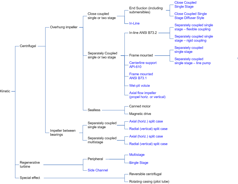
Axial flow pumps are considered to be a type of centrifugal pump. Axial flow pumps are one of three subtypes of centrifugal pumps, the others being mixed flow and radial flow. From the Hydraulic Institute:

Kinetic_uynid6.gif


Axial flow pumps are dynamic pumps, meaning they utilize fluid momentum and velocity to generate pump pressure.

Artisi posted the equation that demonstrates power consumption in pumps:

HP = gpm *ft/3300/eff

Back to the pump curve. If one increases the flow by a factor of 4 (10,000 to 40,000), the head decreases by a factor of 0.52 (38 ft to 20 ft), and the efficiency increases by a factor of 2.7 (from 30% to 82%). If you multiply these factors, 4 * 0.52 / 2.7 = 0.7 (the HP decreases with an increase in flow).

At 10,000 gpm, the brake HP is 320. At 40,000 gpm, the brake HP is 246.

The increase in pumping efficiency with flow is one of the major reasons for the decrease in HP with flow.
 
As bimr says, axial flow pumps have a very marked "sweet spot" at higher flow.

Go away from that zone and things get worse. Axial pumps are more like propellors and my assumption has always been that at higher head requirement, more flow spills back off the blades or creates lots of swirl between the blades. When velocity or flow is high it works well, lower velocity and you run into partial stall.


see or


if you want a bit more theory

Remember - More details = better answers
Also: If you get a response it's polite to respond to it.
 
As I said the mistake is very common but it is still a mistake. Axial flow (propeller pumps)do not use the principle of centrifugal force to pump fluid, which is what the name of the pump refers to. The misnomer leads to much confusion, which can easily be avoided. I know you will find plenty of references to the misnomer. The more technical references take the care to classify both types of pumps under the name roto-dynamic because the is the one characteristic that they both do share. Plenty of people still refer to tin foil. They are technically wrong.
 
Axial flow impellers use the aerofoil principal for blade shape exactly the same as a aeroplane wing, so would you or could ever consider the flow across a wing as being centrifugal.
There will be minor centrifugal forces coming off the blade of an axial flow pump, but this (normally)corrected by the diffusing blades / section of the pump unit which are located directly following the impeller.

It is a capital mistake to theorise before one has data. Insensibly one begins to twist facts to suit theories, instead of theories to suit facts. (Sherlock Holmes - A Scandal in Bohemia.)
 
There is no "mistake", it is the accepted terminology, in the United States marketplace. The terminology does not describe the design principle of the pump and nobody seems to be confused.

There are many intelligent pump experts that use the terminology so it does not cause my nose to get out of joint:

Igor Karrasik's as well as the Hydraulic Institute's definition of a centrifugal pump:

"A centrifugal pump is a simple machine consisting of a set of rotating vanes enclosed within a housing or casing."

books


"An axial flow pump is essentially a high capacity low head centrifugal pump."


per A.J. Stepanoff's "Centrifugal and Axial Flow Pumps":

"Centrifugal pumps comprise a very wide class of pumps in which pumping of liquids or generation of pressure is effected by a rotary motion of one or several impellers. In the early stage of centrifugal pump development, pumping was ascribed to centrifugal forces. Later this class of pumps was extended to include axial flow pumps, and the conception of the centrifugal action of the impeller was inadequate to explain the operation of axial flow pumps. However, treatment of axial flow pumps as a class by themselves was not justified, because hydraulically they represent one extreme of a continuous series of pump types. This continuity applies to both theoretical treatment and design methods. Some intermediate types are called mixed-flow pumps. In these, the flow through the impeller has both radial and axial components and the impeller resembles a ship propeller."


Per "Pumping Station Design" by Garr Jones:

"In colloquial usage in the United States, a "centrifugal pump" is any pump, in which the fluid is energized by a rotating impeller whether the flow is radial, axial, or both (mixed)"
 
To the layman it could / can cause some confusion but that is nothing unusual for the layman, much of the pump terminology cause confusion until such times it is fully understood.

It is a capital mistake to theorise before one has data. Insensibly one begins to twist facts to suit theories, instead of theories to suit facts. (Sherlock Holmes - A Scandal in Bohemia.)
 
This may be out of topic. Another commonly confused terminology is the specific speed Ns. Commonly referred to as pump specific speed which is only correct for a single stage pump.
The actual reference should be to the impeller design or geometry.
 
Status
Not open for further replies.

Part and Inventory Search

Sponsor