Continue to Site

Eng-Tips is the largest engineering community on the Internet

Intelligent Work Forums for Engineering Professionals

  • Congratulations KootK on being selected by the Eng-Tips community for having the most helpful posts in the forums last week. Way to Go!

Basic Dim on Series of Holes

franhd

Mechanical
Aug 13, 2023
10
hole series

Hi everyone,

I'm pretty sure I know the answer to this, but just want to double check here.
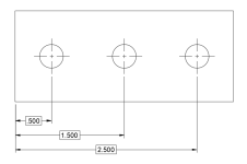
Take the example image above, and you're asked to measure true position of all three holes, with respect to datums A | B | C.

The first hole from left edge will have position measured with .500 as the target.
The next two holes, I would assume you use 1.500 and 2.500 as the target to calculate true position since datum C is the reference datum.
What I don't want to happen is inspectors stacking tolerances from hole to hole and for ex. calculate true position with 1.000 from the adjacent hole.

I don't see too many resources explaining this. Let me know if I'm correct about this or not.
Thanks!
 
Replies continue below

Recommended for you

Hi, franhd:

There won't be any tolerance stacks as the holes are positioned to datum A, B, C. And that is the beauty part of BASIC dimensions.

Best regards,

Alex
 
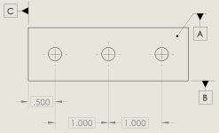
Jassco's correct. You could also change the basic dimensions to all originate from [C] on the drawing, if you're not confident that your inspector will interpret the original correctly.

asdf
 
Thanks Jassco!

Mech1595: I could also do it that way, the problem is when it gets to 10 holes or even 20 holes in a row.

But I'm glad to know that my beliefs are confirmed.
 
Hi franhd,
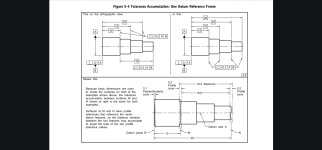
You can refer to this figure from ASME Y14.5 to point out there is no tolerance stack on a chain of basic dimensions:5-4
 
It shouldn't be an issue, really. This is a foundational idea in GD&T and there are a lot of resources to back up the idea that there's no accumulation of tolerances across those three.
 
Is anyone concerned by the fact that there is no target to meet and no tolerances to stack without FCF anyway?
 
If you want to make your drawing needlessly ambiguous and confusing (in practice hardly any inspector cares about GD&T) then go ahead and do it like you've shown. I tend to prefer simple and obvious.
 
CheckerHater, there's no concern about that because the OP stated that we are "asked to measure true position of all three holes, with respect to datums A | B | C."
No number given, but we get the intent.
 
Hi, elbaz_:

I am surprised by this statement below:

"in practice hardly any inspector cares about GD&T."

GD&T is a language that describes products and their specifications. One of purposes in using GD&T is to get rid of ambiguity. Professional inspectors inspect products per prints whether they are done in accordance with ISO 1101 or ASME Y14.5.

Hi, franhd:

If you have a lot of holes, I recommend that you use BASIC ordinate dimensions.

Best regards,

Alex
 
I had this same discussion with an inspector who kept failing parts by re-zeroing on each hole to inspect the next one, instead of setting up on the datum features as defined on the drawing and inspecting each hole independently in that datum reference frame. He insisted that he knew what the engineer wanted. I pointed out that the engineer's name was in the signature block and if he thought that he was correct, then call the engineer and get the drawing changed. I never found out if he did make that call; the manufacturing engineer I was supporting had been facing imminent self-managed hair loss after making yet another CNC fixture that was getting first article parts rejected. I told him what was happening and he seemed the sort to handle his own problems once he knew the source.
 

Part and Inventory Search

Sponsor