Eng-Tips is the largest engineering community on the Internet

Intelligent Work Forums for Engineering Professionals

Beam bending refresher 2

rcfraz37

Mechanical
Oct 9, 2024
5
0
0
US
So its been a while since I did beam bending back in school and now I'm having some trouble.

The regular equations, I believe, assume fixed ends, at least the ones I can find. Trouble is I am looking for the length by which a beam gets shorter as it bends, and my end points rotate.
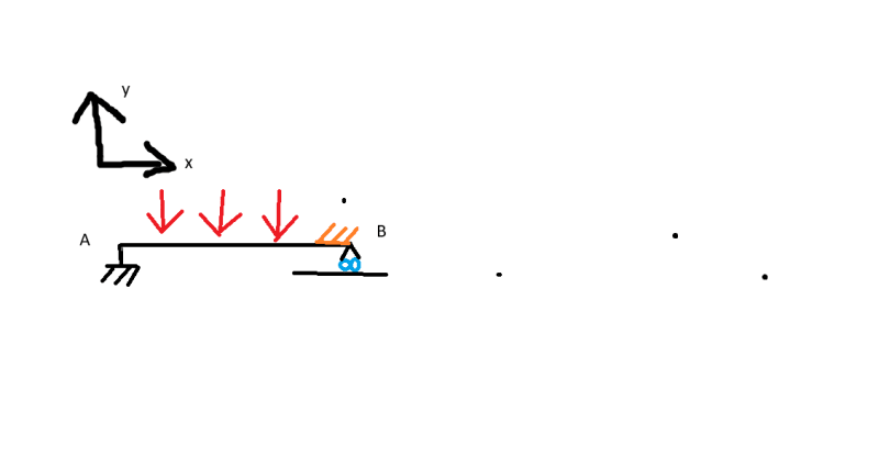
See pic
A is rigidly affixed translationally but allows the beam to rotate freely. B prevents Translation in the Y direction but no other Direction.

I'm trying to make my design driven because we keep changing materials so I'm going with F= force (assuming a uniform load across the length) L= length I=moment of inertia and E= modulus of elasticity.

I tried finding the deformation with (5*F*L^4)/(384*E*I)=d. and then the slope with w*L^3/(24*E*I). and using those to back out the geometry of the arc but the math isn't right.

Am I heading in the right direction?

Any help would be a life saver
 
 https://files.engineering.com/getfile.aspx?folder=15f48676-a670-4e27-a58b-969236dec5b9&file=beam_bending.png
Replies continue below

Recommended for you

look for simply supported beam and "superposition".

your beam looks simply supported to me. Each of your point loads can be applied separately and summed. Solution for a simply supported beam with a point load. But this way is hard to superimpose deflections ...

another way some people do it is to replace the loading with an equivalent distributed load ... sum the load applied F = (P1 + P2 + P3 + u*l) and uniformly distribute over the whole span, F/L.

your deflection equation ... δ=(5wl4)/(384EI) is for a simply supported beam with a uniformly distributed load.

"Wir hoffen, dass dieses Mal alles gut gehen wird!"
General Paulus, Nov 1942, outside Stalingrad after the launch of Operation Uranus.
 
That's not quite my issue if I understand your answer. I'm getting the deflection in the y direction fine. The issue is with that Y deflection the length in the X must contract. that's what I'm looking for. There is only 1 uniformly distributed load across the beam.
 
the arc of the deflected beam is a quartic, x^4, but maybe simple enough to model as a circular arc.

then you know the arc length (= L), and arc length = theta (radians) *R
then what angle given the deflection ... you know, two sides of a triangle R and R-d, third side, x, = sqrt(R^2-(R-d)^2) or x*R = sqrt(1-(d/R)^2) = sin(theta)
and R*theta = L/2
the displacement of the end is so tiny that the typical approximation sin(theta) = theta leads to x = L/2 (and no longitudinal deflection of the end)
but there is a small deflection found by working through, iterating I guess.

but this small deflection is probably incorrect, based on the simplification of the loading.


"Wir hoffen, dass dieses Mal alles gut gehen wird!"
General Paulus, Nov 1942, outside Stalingrad after the launch of Operation Uranus.
 
what are you doing that makes this tiny displacement critical ?

"Wir hoffen, dass dieses Mal alles gut gehen wird!"
General Paulus, Nov 1942, outside Stalingrad after the launch of Operation Uranus.
 
so people are assuming this is a very small load, or a small displacement, it is not. I think the simple beam framework is the problem but i don't know where to look for something more complex.

this is a 160in long catch that is loaded evenly with load up to 2000lb (I'm trying to get this down). I want the deflection at that point so that it can slip its catch and not be restrained at point B anymore. releasing the load safely.

I really appreciate all the help though. rb1957, I gave that a shot and the results I got didn't quite make sense with what I'm expecting so I think the simplicity of the system is causing problems.

are there any names for what I'm trying to do? complicated beam bending? Thanks again
 
non-linear, large displacement beam theory.

simplest method would be to make a beam model in an FE code and run a non-linear large displacement solution.
 
Make the end support adjustable, which you will need anyway, and run a test. Keep in mind that there will be an incredibly small area as one nears the release point upon which 1000 pounds will rest before finally escaping. It will also change with temperature differences between the bar and the supporting structure which may be subject to thermal transients even if of identical materials.

Things like this are better operated with sequential triggers where the full load is not applied to the release mechanism - example a mouse trap where the trigger bar sees only a fraction of the resisted trap bar load applied to the point of trigger contact.
 
this is a 160in long catch that is loaded evenly with load up to 2000lb (I'm trying to get this down).

What physically does this actually look like?

And what do you mean by

I want the deflection at that point so that it can slip its catch and not be restrained at point B anymore. releasing the load safely.

 
Right I’m going to guess that the orange coloured lines on the diagram is the catch that the OP refers too and that at the 2000lb the beam shortens sufficiently in the axial length to release it from its catch and the load runs off the beam, maybe a diagram with some labels on it and a proper description of what the beam is intended to do might save of all having to get our crystal balls out.

“Do not worry about your problems with mathematics, I assure you mine are far greater.” Albert Einstein
 
yeah, what are you trying to do ? do you want B to release ? or release at some specific deflection ? (have the end translate inside of a socket ?)

ok your "catch" (whatever that is) is 160" long, and the load is 1 ton. How stiff is the beam, since this controls deflection and the very small translation ? If you need to be that precise then drop the assumption of the UDL, and load the beam with your loads. Most beam solvers won't help you (pretty much no one looks at this point), so you're stuck doing integration (it ain't that hard, I can set something up for you ... SS beam with three point loads ?).

"Wir hoffen, dass dieses Mal alles gut gehen wird!"
General Paulus, Nov 1942, outside Stalingrad after the launch of Operation Uranus.
 
The image tool is not that hard to use.

beam_bending_vi91fz.png
 
from MJ's link ...
The exact change is minimal. For a beam whose deflection y(x) has been defined in terms of x, the change in "length" can be determined by the slope function θ(x)=y′(x)

ΔL=−1/2*∫L0(θ(x))[sup]2[/sup]dx

(Ref Roark's formulas for stresses and strains, 8th edition), Eq. 8.1-14
∫L0 = the integral from 0 to L of the slope of the beam theta(x) ^2
theta(x) is a function, the value you have is the maximum slope (at the end). slope will be a cubic in terms of x.

I suspect it is so small that you won't be able to build it (reliably) and will have to fine tune things (run a bunch of tests).

define the loading, and the beam section properties or the design constraint you have (ie I need this translation to be 0.001", as I imagine you're designing your beam property to suit some design criteria).

"Wir hoffen, dass dieses Mal alles gut gehen wird!"
General Paulus, Nov 1942, outside Stalingrad after the launch of Operation Uranus.
 
Perhaps the application is more like a leaf spring that a beam.

Leaf springs, as used in automotive suspensions, include a "shackle" to deal with the lengthwise deflection that the OP seems to want to rely on.

LeafSprings_72_oqshwj.png
 
Not understanding much about this, but ... once the beam slips it's catch then it isn't loaded and returns to undeformed length? Seems like a jam up.
 
Questions:
1. What happens when the beam slips the catch? Does the beam suddenly drop?
2. How far does the loaded beam fall? A 2000lb load plus the weight of the beam itself is substantial.

If you want a beam fixed translationally but free to rotate on one end, your beam will need a pinned joint on one end and be simply supported on the other. Deflection wise, you can probably treat the beam as simply supported on both ends.

What type of beam are you planning to use? If you want to control the deflection of the beam, you will need to work backward from the amount of change in length due to deflection and arrive at section properties that will give you that deflection.

Also, there will most likely be friction considerations which can be hard to predict.

 
Another thing to consider is using a lower modulus of elasticity material, such as an aluminum structural member. Roughly 1/3 the modulus of steel will provide triple the deflection for similar sections.
 
Back
Top