Continue to Site

Eng-Tips is the largest engineering community on the Internet

Intelligent Work Forums for Engineering Professionals

  • Congratulations KootK on being selected by the Eng-Tips community for having the most helpful posts in the forums last week. Way to Go!

Beam with cantenery action

Status
Not open for further replies.

JAE

Structural
Jun 27, 2000
15,444
We have a project where we are checking a long steel tube that is on top of a steel plate wall - essentially the tube is the wall cap that goes around the perimeter (4 walls) of a steel tank.

The tank is filled with water and imparts lateral pressures on the tank's four walls. This creates an outward uniform force on the tube on all four sides.
The tank is about 10 ft. wide x 36 ft. long.

The tubes will naturally bend outward and have axial tension in them due to the orthogonal walls with their outward uniform load.

The question is - we need to determine the stress in the long 36 ft. tube due to axial, bending and perhaps any axial effect from what appears to maybe be a cantenary effect. How to do this?

Roark's has essentially a case where a beam is rigidly fixed at the ends with a uniform load on it.
It is labeled as Table 8.10, item 3 (Beams restrained against horizontal displacement at the ends - ends pinned to rigid supports, uniformly distributed transverse load on entire span.

However, the end walls of this tank are not perfectly rigid and will bow inward a bit with the cantenary tension on the long tube, right? So this will have the effect of reducing the axial tension in the tube a bit. Roark's does NOT have an item with axial spring supports at the ends.

We've modeled this in RISA 3D and get results but something tells me that the RISA results may not include non-linear effects of the cantenary action in this tube due to variations of the end supports with regard to axial loads.

I seem to understand that RISA does PDelta analysis but that only includes PDelta effects perpendicular to the member and does not include axial PDelta effects.

Any thoughts on this? I've inserted essentially the beam problem in a sketch.
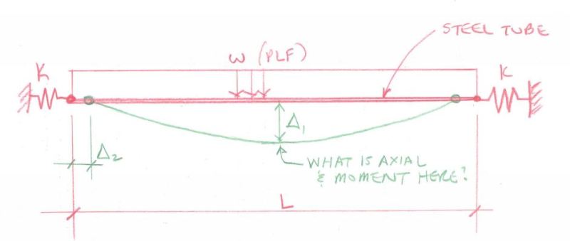
Tube_Cap_Sketch_lqk13h.jpg


Check out Eng-Tips Forum's Policies here:
faq731-376
 
Replies continue below

Recommended for you

Thats tricky. I'm not too familiar with RISA, but I suspect that you won't be able to treat the member as a beam (moment and shear) and a cable (tension due to cantenary action) at the same time. This is probably true for most analysis programs.

Some other thoughts - if you develop enough deflection to get true cantenary action, you're probably exceeding the "small deflections" assumptions in basic beam theory that you would use to get your moments and shear. Also, if you get enough deflection for cantenary action, are you going to have serviceability issues?

Are the tubes fixed to each other at the corners? That will add some moment at the ends of the beam in your sketch.

I think I would approach this problem by looking at it is a bending member only and check deflections. If the deflection was excessive and exceed the "small deflections" assumption, then I would treat it as essentially a cable and ignore the beam effects. Obviously the true answer lies somewhere in between those two methods, but that is beyond my analytical capabilities.
 
1) use of "cantenery" is not correct. Catenary means deflections under self weight (only).

2) why go to the double cantilever beam ? why not simply supported as a (presumably) conservative model for a beam with a UDL ?

3) what would be the UDL ? presumably the loading is an enforced displacement (I can't see this rod reacting much of the applied load). Maybe Roark has this deflection in his plates section. His reference for plates is work done by Moody as part of the Corp of Engineers ... google "moody rectangular plates" (seriously).


another day in paradise, or is paradise one day closer ?
 
Hmm. One possibility for a hand calculation:

1) Disregard wall below the HSS acting as a shear wall of sorts.

2) Calculate deflection in the HSS based on pure bending and uniform load.

3) Switch the beam model to a pair of rigid bars connected in the middle with a pin joint.

4) Use the tension that you know exists at the ends, and the deflection from #2, to calc a faux point load at mids-span that keeps the two bar model in equilibrium under the imposed displacement.

5) Switch back to the beam model, apply the faux load from #4 reversed, and calc some deflection the other way.

6) Go back to step #3.

Hopefully, a few iterations through steps three to six will close with a reasonable amount of effort. If that happens, you should have an equilibrium condition that you can design to and is probably about as accurate as anything else.


I like to debate structural engineering theory -- a lot. If I challenge you on something, know that I'm doing so because I respect your opinion enough to either change it or adopt it.
 
rb1957 - cantenary is deflections under gravity....agree.
The tube is simply deflecting under a "similar" uniform load - whether it is gravity due to self weight or lateral load due to constant water pressure the tube "doesn't know".
So it is a similar problem - a long skinny, relatively flexible tube under constant load yes?
Or does the gravity load have a partial axial component when the "cable" droops?

Check out Eng-Tips Forum's Policies here:
faq731-376
 
KootK - the wall below is a deck-like wall that would flex like an accordion with axial strain changes in the tube so definitely did ignore any possible shear wall effect.


Check out Eng-Tips Forum's Policies here:
faq731-376
 
Back to the structural analysis:

CANPRO said:
I suspect that you won't be able to treat the member as a beam (moment and shear) and a cable (tension due to cantenary action) at the same time. This is probably true for most analysis programs.

Any (half-decent) finite element analysis program that allows a beam element to resist an axial force and also purports to do a geometrically non-linear analysis should be able to capture this behaviour. The continuous updating of the element stiffness as the beam deflects is central to the idea of geometrically non-linear analysis and this should result in your structure transitioning from resisting loads through bending action to cable action.

Perhaps you haven't subdivided your mesh enough to capture this deformation? Also be careful with load increments, it may not work to apply all the load at once, better convergence will be achieved if you slowly apply the load in small increments.

Here's a quick example in Strand7, in which a slender beam with 20 elements is loaded with a UDL:

Capture_rg9duc.png


Capture1_g3yefl.png

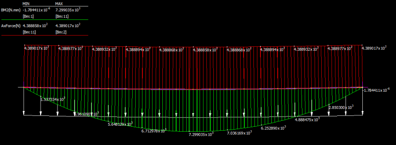
Axial force diagram (red) and bending moment diagram (green) with relatively small loading.

Capture2_bz6jv2.png

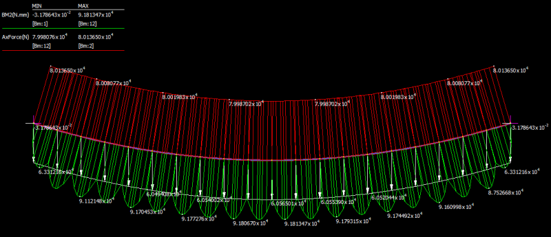
Load here is 1000 times higher than the first diagram - bending moment has only increased by a factor of 10 and is now represents a more constant distribution along the length of the beam; primary resistance of load is through axial force.

Capture3_g9usdm.png

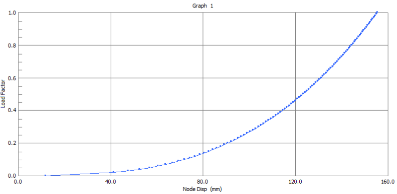
Load displacement diagram - the stiffening of the structure resulting from cable (membrane) action is apparent.
 
That's an impressive bit of sport engineering HOTL.

JAE said:
KootK - the wall below is a deck-like wall that would flex like an accordion with axial strain changes in the tube so definitely did ignore any possible shear wall effect

That's what I like to hear. Keeps things simple. In that case, I definitely like the method that I proposed (bias of course). Might be a good hand check if nothing else.

I like to debate structural engineering theory -- a lot. If I challenge you on something, know that I'm doing so because I respect your opinion enough to either change it or adopt it.
 
I get it, but it "simply" a beam with a distributed load, or more likely a distributed enforced displacement (since I don't see it really reacting much of the load ... yes, yes, the enforced displacement means it'll react some load ...). And this is why I first questioned the double cantilever assumption ... I see the corners opening up, as the rectangle ovalises under the water load; I don't see the reflex curve required for a double cantilever. I think you can find the max deflection of the top edge of the side of the tank, then assume a sin wave deformation, and figure out the internal moments and shears ...

another day in paradise, or is paradise one day closer ?
 
I did a quick analysis with a 36-foot square frame of tubes with outward uniform load (just made up a load), with three different tube sizes: 3x3x1/8, 6x6x3/8, 8x8x1/2. Running it through a linear, PD with small disp, and PD with large disp. The linear and PD small disp gave me basically the same answers. PD with large disp gave me slightly larger axial force for larger tubes and significantly larger axial force (about 20% larger) for the small tube.
 
On terminology:
It's catenary, not cantenary.
I disagree that the term only applies to chains hanging under gravity loads. That's where the name came from, but the catenary effect applies to any system where significant tension is generated by transverse loads on an element with restrained ends.

On the analysis:
I agree with handofthelion. The p-delta effect is essentially the same for tensile and compressive loads (except in tension it tends to reduce the deflection, rather than increase it).

It seems to me that the easiest way to model it would be to do a 3D analysis of 1 corner with symmetry boundary conditions. Include the steel plate as well as the top tubes, and apply the hydrostatic pressure.

Doug Jenkins
Interactive Design Services
 
I think the loading of the tube is driven by the deflection of the side wall. Of course in deflecting it'll react a small amount of the load. I think it'd be reasonable to apply the max deflection of the wall due to the pressure. If you want to refine it, you could extract the internal shear reactions and determine the equivalent amount of water, ie an equivalent depth, and remove this from the deflection calc, and iterate.

Thinking about the corners ... I'd use a single pin joint and remove any fixity. But there's an interesting question ... what is the angle between the sides doing ? how to analyze ??

Of course the best (most accurate) answer is the FE the heck out of it.

another day in paradise, or is paradise one day closer ?
 
rb1957 said:
I think the loading of the tube is driven by the deflection of the side wall.
Agree.

The problem sounds like the mirror image of the top wale ring of a rectangular cofferdam. In this case, pressure in the tank pushing out, versus pressure on the outside of a cofferdam pushing in. I'm sure its more complicated than that, but believe rb1957's approach is effective.

[idea]
[r2d2]
 
If the members have zero capacity to resist bending moment, they act like cables. None is a catenary. They all deflect in a parabolic shape because the load is uniform.

The tension at midpoint of the long cables is w(36)[sup]2[/sup]/8d1 = 162w/d1 where d1 is the deflection at midspan. Deflection d2 of each half endwall results from the force 162w/d1 - 5w acting on it. Deflections d1 and d2 must be geometrically consistent with the change in length of the member.


BA
 
I think a part of this problem has been made too complex. I think determining the tension in the tubes is fairly straight forward - it can only be what is supplied by the adjacent wall. If the uniform load on the tube is W, then the tension in the 36' long tube must be 1/2*W*10'. Now for analyzing the 36' tube, you have a uniform load, and axial loads applied at the end. If you assume initially that the horizontal deflection is zero, the first iteration is basic statics. If the tubes are fixed together at the corners this step might get a bit more tricky.

The first iteration will give you a deflected shape and moment/shear/tension along the length of the tube. Using the deflected shape, and any change in length due to axial loads, you can determine the horizontal displacements and run a second iteration.

handofthelion - that looks like a great tool. I could have used that in the past. In RISA I just modeled a W4x13 spanning hundreds of feet with a huge load on it and it returned zero axial. That's exactly what I expected and the results I've gotten from similar programs in the past. Granted, I rarely turn to these programs in my day to day work and I'm sure I only use a fraction of their capabilities, so maybe I can do this in RISA. I'm not familiar with strand7, is it comparable in capabilities to RISA and similar programs?
 
I’m not sure RISA accounts for an axial tension p-delta working to straighten a bending member but it does p-little delta for compresion. RISA doesn't take into account FE plate p-delta according to the manual.

I would use the tank generator module and make the walls plates that are plane stress to get the catenary type tension forces from the walls onto the tubes. Then design the tubes as normal bending and axial members without any catenary action of the tubes themselves. There may be some straightening effect from tension on the tubes if RISA doesn’t do p-delta for tension.
 
And I just tried modeling that in RISA and got enormous wall deflections assuming a 10 ft deep tank with 0.5" walls so maybe that is not a good approach...
 
@CANPRO, I've not used RISA before but a quick look at their documentation - looks like they're doing a pseudo-non-linear analysis by using an algorithm to account only for a reduction of flexural stiffness due to P-Delta effects. Strand7 seems to be more of a general finite element program whereas RISA seems to be more of a design program(?). Strand7 therefore implements a generalised geometrically non-linear analysis that is not limited to certain effects.

my structural engineering blog
 
The tension will cause a P-(little delta) moment that will reduce the overall moment. I would start with the B1 factor from the AISC B1-B2 approach.
 
Status
Not open for further replies.

Part and Inventory Search

Sponsor