Eng-Tips is the largest engineering community on the Internet

Intelligent Work Forums for Engineering Professionals

BEHAVIOR OF WELDED PLATE CONFIGURATION 1

Status
Not open for further replies.
Replies continue below

Recommended for you

No! The shear is constant and the moment is variable.

In a combined section, horizontal shear would be carried continuously along the faying surface of the two plates. In the pictured arrangement, all of the horizontal shear is carried by the weld at each end (neglecting friction).

In a combined section, bending stress would vary linearly along the beam with maximum tension at the top and maximum compression at the bottom. In the pictured arrangement, the upper plate would be primarily in tension while the lower plate would be primarily in compression.

BA
 
In order for them to behave like a combined section you need a shear connection along the length. Just like BAretired is saying.
 
Thanks for the quick response. I didn't think it would behave like a combined section, but with the weld at the free end, I wasn't sure since the plates aren't really free to slip independently.
 
Hello

Two plates can be bolted together and act like one, if there are enough bolts or welds per a given lenght to handle the shear. There is a calc for this with shear flow. Girders have been made using rivets.

In the given example it does look like the plates may seperate, but there are not fully free to slip
 
I would think the plates would share the load (equally)....but it wouldn't be through shear flow. (I.e. it would be because the weld at the end would transfer some of it (vertically) below.)


TEDstruc said:
but with the weld at the free end, I wasn't sure since the plates aren't really free to slip independently.

I think that you instincts are pretty good here. To be perfectly composite, I believe that you need horizontal shear resistance at all locations where you have vertical shear. Since you clearly do not have that, you do not have perfectly composite behavior.

However, just because you do not have perfectly composite behavior, that does not mean that you don't have significantly composite behavior. A ubiquitous example of this is the case of steel beams made "composite" with attached deck slabs. In that scenario, the shear studs often are not distributed in a fashion consistent with shear demand along the length of the beam. So, again, you don't have perfectly composite behavior. You do have significantly composite behavior though which, of course, is why we bother.

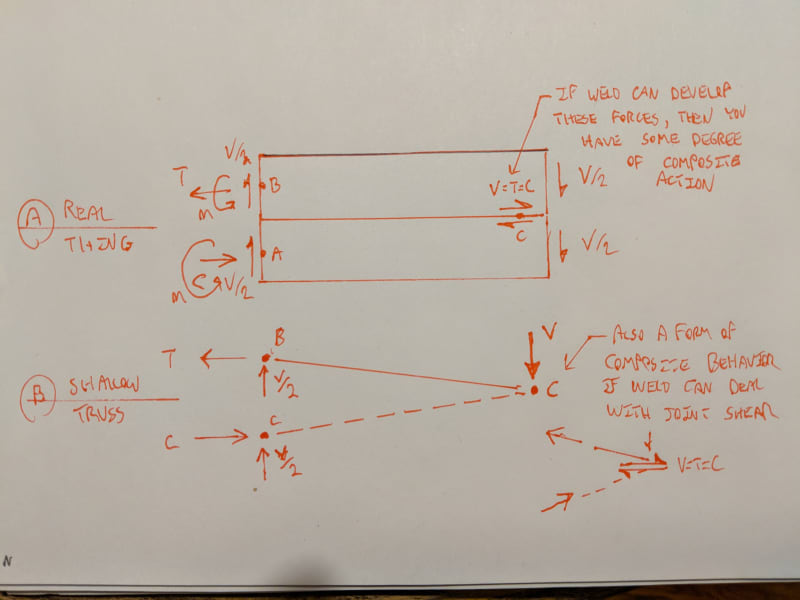
The sketches below take two different approaches to demonstrating a significant degree of composite behavior for your example:

A) This is what I would consider to be a realistic free body diagram of the situation. The presence of the weld shears developed at the tip, acting over the 1/2 thickness eccentricities of each plate, produce a degree of composite behavior that creates results significantly different from the "two cantilevers sharing the load equally" model.

B) Another way to look at this is as a shallow truss with the tip joint representing the horizontal shear transmitted by the weld there. Obviously, this is also a significant improvement over the "two cantilevers sharing the load equally" model. This probably under-emphasizes the effect. Points B & C could probably be considered to be nearly at the outer extremes of their respective plates. And it's that apparent increase in effective flexural depth that reflects a degree of composite behavior.

2018-07-24_21.54.05_cc7ysb.jpg


I like to debate structural engineering theory -- a lot. If I challenge you on something, know that I'm doing so because I respect your opinion enough to either change it or adopt it.
 
Hello. One example of where shear flow calcs used to be done is with a girder joined together by rivets instead of welds. This is how bridges where often made. But in the case of the girder you have a web, so no bolts or welds are not on the neutral axis. The top plate was joined to the web with angles and rivets. So connection was not continous

Shear flow= Q=A x Y. Where Y is dist from neutral axis. A is area above the horz plane that the rivets are transmiting the shear. Then use calc q= (V x Q)/Intertia to get force/unit length of shear at that plane. The bolts or 'skip welds' must handle this load. But in this particular case the welds (or rivets or bolts) are at the neutral axis, so Y=0. So I am not sure which formula would be used, without looking deeper. In any case it does not look like a stable structure and has a limit on what loads in can handle. Most probally the buckling load of the lower plate in compression. Assuming the composite is acting like a cantilevered beam with load at end.

I also made a assumption that the top plate was connected to the wall some how. I am not the only one who made that assumption. Technically, the top plate would handle no tension or moments at the wall if the weld is only to the bottom plate, as shown.
 
I'll second dik's comment - excellent explanation KootK. Just to expand on the composite bridge girder comparison, currently in the AASHTO bridge spec, there have to be shear studs at least every 2ft along the span for composite action to be considered. However, based on new research, there is a proposal to increase that 4ft, so it appears that significant composite action occurs with more widely spaced connection points than previously thought.
 
as pointed out by KootK, there is some partial composite action involved along with individual bending of each pl.....the question in my mind is what force would one design the weld @ the tip for?....at first glance, I thought that if one designed it for the shear assuming full composite action that it would be conservative and ok....but, on further thought. there is also the force from the individual bending of each pl being constrained to act as one @ the tip....I have no clue at the moment on what the magnitude of that would be.....
 
..the question in my mind is what force would one design the weld @ the tip for?....at first glance, I thought that if one designed it for the shear assuming full composite action that it would be conservative and ok....but, on further thought. there is also the force from the individual bending of each pl being constrained to act as one @ the tip....I have no clue at the moment on what the magnitude of that would be.....

There would be the force from the plates sharing the load (about half), the (limited) shear flow (which I kind of question with that fixed support), and a bit of moment as it acted sort of like a mini-moment frame. You'd probably be covered just by considering the first two.
 
SAIL4 said:
the question in my mind is what force would one design the weld @ the tip for?

I'd size the weld just as I presented it in the shallow truss model above. With a conservative estimate of the effective flexural depth as shown, the shear in the weld should be sufficiently conservative as well. The load sharing component will be negligible relative to the faux composite demand.

I like to debate structural engineering theory -- a lot. If I challenge you on something, know that I'm doing so because I respect your opinion enough to either change it or adopt it.
 
The load sharing component will be negligible relative to the faux composite demand.

I'd have to question that because I was messing around with a FEA model on this in the morning (while my caffeine was taking affect)....and the piece that connected the 2 cantilevers had a axial load of V/2 (by your sketch).

 
WARose said:
.and the piece that connected the 2 cantilevers had a axial load of V/2 (by your sketch).

V/2 is what I would expect for that component. I'd probably just design it for V. My point is that I would expect the shear flow component to be much larger than that and, looking back at my shallow truss model, that seems pretty apparent to me.

I like to debate structural engineering theory -- a lot. If I challenge you on something, know that I'm doing so because I respect your opinion enough to either change it or adopt it.
 
V/2 is what I would expect for that component. I'd probably just design it for V. My point is that I would expect the shear flow component to be much larger than that and, looking back at my shallow truss model, that seems pretty apparent to me.

According to my model, it depends on how long that connector is. The shorter it is, the smaller it is. (They are about equal for a very short connector element. In some cases the axial load is higher than the shear for a very short element.)


TEDstruc, based on your sketch, it appears you have a Complete-Joint-Penetration Single-Bevel-Groove Weld at the bottom plate connection to the support. This connection could be modeled as a fixed connection to the support for the bottom plate only. To clarify, from a constructability standpoint, the only way to accomplish the welds as detailed would be to first weld the bottom plate to the support and then attach the top plate with a fillet welt along the end of the support where the load is applied as shown. Therefore, there is nothing connecting the top plate to the support at the supported end and the reaction at point B illustrated in KootK's Sketch A does not exist as currently detailed in your sketch. In order for KootK's sketch to apply, you would have to weld the top plate and bottom plate to the support!
 
WARose said:
According to my model, it depends on how long that connector is.

It needs to be recognized that my weld recommendation and my assessment of the relative importance of various things is all based on my model. And that was a model that was always intended to be simple and conservative, not necessarily accurate. I would not expect my model to show great agreement with your FEM model. Seeing as you've already got this FEM model set up, and it's surely our most accurate window into the true behavior, just how composite is this thing anyhow? My work doesn't speak to that. Rather, it simply demonstrates the logical necessity of there being some degree of composite behavior.

Structural Wiz said:
In order for KootK's sketch to apply, you would have to weld the top plate and bottom plate to the support!

Only OP can say for sure but took the idiosyncrasies of the fixed end welds to be simply graphical faux pas. I figured that either A) it was a purely theoretical thing and the welds didn't matter or B) it's a practical thing and it's probably just the reinforcement of an existing upper plate that is already fixed into place with some kind of welding. Yeah, the bottom weld is technically impossible as shown but all you have to do is flip the triangle around and you're back in business.

BAret said:
How did we get V = T = C on Kootk's Sketch B?

V, in that instance, ought to have been Vh for horizontal shear. True of both sketches really.

I like to debate structural engineering theory -- a lot. If I challenge you on something, know that I'm doing so because I respect your opinion enough to either change it or adopt it.
 
Status
Not open for further replies.
Back
Top