Eng-Tips is the largest engineering community on the Internet

Intelligent Work Forums for Engineering Professionals

  • Congratulations waross on being selected by the Eng-Tips community for having the most helpful posts in the forums last week. Way to Go!

Bending stress and deflection on a beam with composite cross sections

Status
Not open for further replies.

blkfrd

Electrical
Jul 3, 2005
15
US
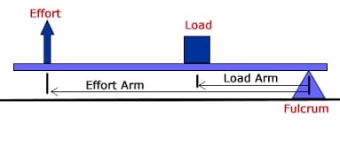
I am analyzing a system that can be modeled as a 2nd class fulcrum. The link below about 1/3 of the way down the page shows an example of a 2nd class fulcrum.

2nd class fulcrum Link

The part that makes up the beam is a composite part made up of a turnbuckle (see link below), threaded tube and a rod end/heim joint that have different cross sections. The beam has a turnbuckle where part of it is a solid male LH threaded rod and part of is a female RH threaded tube. The male portion of the turnbuckle threads into a different threaded tube and the female portion of the turnbuckle has a male threaded rod end/heim joint screwed into it.

Turnbuckle Link

I know the fulcrum arm length, load arm length load, load amount and the moment of inertia of each of the individual portions, but i'm not quite sure if I can calculate an overall moment of inertia of the beam to analyze the stress and deflection of the entire beam as a whole or if I need to determine the load/bending moment at each unique portion of the beam and analyze each section of the beam separately. Any help would be appreciated. Thanks


TC
Comm and GPS Systems Engineer
 
Replies continue below

Recommended for you

A sketch would be helpful.
Note that for a composite beam to act as a single beam, you need shear transfer between the pieces.
 
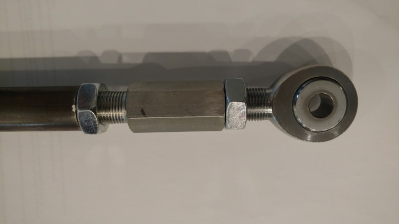
Here is a pic of what makes up the beam. Threaded tube, turnbuckle and rod end with two jam nuts. The force is in the downward direction and the force is applied over the tube section on the left side of the pic. The threaded rod portions have the lowest moment of inertia. What i'm trying to figure out is if there is a way to determine an overall moment of inertia for this beam or if I need to look at stress and deflection of each segment individually or something else.

composite_beam_o6rbmm.jpg


TC
Comm and GPS Systems Engineer
 
Stress is straight forward. The bending stress at a section would use the section modulus at that section and the bending moment at that section.

Deflection is more difficult. I'm guessing others can help more than myself for that.

I wouldn't call this a composite beam. A composite would generally be thought of as having different materials in the same cross section.
 
Thanks for the bending stress info. Before I posted, I looked for a better word than composite whose meaning is "made up of various parts or elements" which fits, but "compound" would also work.

Initially I went to the link below to calculate the system in a static condition. Its requires a second moment of area (Moment of Inertia) for the calculation. The Moment of Inertia of each section is as follows: The tube is .047, the threaded rod is .0075, the female threaded portion of the turnbuckle is .033 and I approximated the rod end by taking an average y axis thickness and came up with .043. I then took the length of each section and weighted it accordingly and came up with an overall Moment of Inertia of .035. I don't feel confident that this is a correct way to go about analyzing this.

Simply Supported Beam Calculator Link


TC
Comm and GPS Systems Engineer
 
To get a fully detailed answer, you need to calculate each part independently.

A 'composite' beam is one where two different materials are used to make up the beam cross section.

Yes, per the dictionary definition of the word 'composite', it seems that it should apply here, but in the world of structures 'composite beam' has a very specific meaning which does not apply to this arrangement of part.

How long is the arm in total? Unless it is very short, the hollow tube is going to account for the vast majority of the deflection of the whole assembly.

If the hollow tube accounts for a large percentage of the total length of the assembly, calculate the deflection in the tube only. This is very easy. The longer the tube is relative to the turnbuckle assembly, the closer this answer will be to reality.

Calculating the loads of the rod end and turnbuckle are relatively simple, based on all the information you say you have. Model the rod end as a solid cylinder with an OD of the minor diameter of the thread, and model the turnbuckle as a hollow cylinder with the ID equal to the major diameter of the thread. Add stress riser factors to these calculations (to account for the threadform) if you are doing something safety-related.
 
Using the pic below, the load arm is 5.5 inches long and the effort arm is 9.375 inches long. The distance between the effort and the load is 3.875 inches long and this part of the beam is very rigid and i'm not concerned about the deflection or bending stress there. The load arm is where the beam is made up of the parts seen in the pic in the previous post (tube, turnbuckle and rod end). The weakest portion is going to be where the threaded rod segments are. The moment of inertia of the surrounding parts is 5 to 7 times more that the moment of inertia of the threaded rod segments. I could probably assume that the stress and deflection is going to be concentrated on the threaded rod segments. I'll determine the force and bending moment on these segments and calculate the stress and deflection.


2ndclassfulcrum_ydleuc.jpg


TC
Comm and GPS Systems Engineer
 
Is your sketch badly out of scale ?

What is the nature of the load?
Unless essentially static or very small, I'd be very concerned about the jam nuts loosening, and the detail between the thread and hex body of the turnbuckle.

Are the threads Left Hand and Right hand, so lengthening/shortening can be done leaving the ends of the effort arm attached?
As a first cut using that online calculator I'd check the stress entering the threaded rod moment of inertia, and probe for X at the end of the tube under the jam nut.
How did you arrive at a value for the threaded rod moment of inertia?

 
So you have a beam with different cross section, so follow Brian22 recommendation for bending stress but the discontinuity would need some factor at those sections. Machine Design text will detail those factor involving bending situation. For deflection, I would develop moment equations along the length, bearing in mind that the moment of inertia will change at the discontinuities and double integrate for deflections. My reference is from a reprint from the May 8, 1972 issue of Design News, a Cahners Publication. The title of the reprint is Design of Nonuniform Beams authored by T.V. Seshadri, Chief Engineer of Fruehauf Corp, Detroit Mich.
 
If I wanted (needed) to know the deflection of the end of that rod end (first I'd wonder why, but you've already done that) I'd test it. Analytically summing each section would be a long exercise and probably not accurate.
 
"I then took the length of each section and weighted it accordingly" ... how did you weight the sections. deflection due to a point load is proportional to ML^2/EI, or PL^3/EI

another day in paradise, or is paradise one day closer ?
 
This assembly won't act according to normal formulas because those assume stress continuity via material continuity, but the threads produce gaps and the ability to maintain those gaps depends on the amount of preload applied by the jam nuts.

To get an accurate evaluation it is easier to just set up an experiment with dial indicators to measure deflection.
Getting stress is more difficult as the transfer of loads from part to part depends on knowing the geometry very precisely.

Typically such assemblies are only used in tension critical applications where side loads are insignificant.
 
Yes that diagram was something I found on the internet. It does not depict the actual location of where the load is but it was something I just grabbed off the internet to illustrate what I was talking about.

The parts that I included in the picture are all three quarter inch parts. What I'm trying to figure out from this exercise is if I can use 5/8 because producibility of the entire part will be simplified for reasons I won't go into right now because that's a whole other subject.

This type of setup is common in the aftermarket automotive industry for this sort of application. I know the 3/4 Hardware will work but I'm not sure about whether there's adequate strength there for the 5/8 Hardware

I will do some testing on it but right now I'm trying to do some analysis on it before I conduct any testing

TC
Comm and GPS Systems Engineer
 
Aftermarket automotive + rod ends in a tubular link

Type II lever

This is some type of control arm, probably. If it is a control arm, you have to deal with impact loading, not just simple forces; making a hardware sizing decision based on simple forces only is a really, really bad idea.
 
It certianly is...I am analyzing it statically first to see if 5/8 hardware passes muster, then consider dynamic loading. It is an upper control arm application with a spring perch for the coil spring so the load is variable and there is shock load to consider too. I don't have much hope in the 5/8 hardware being adequate although production would be simplified (because weld bungs for 1" OD DOM having 5/8-18 thread are commercially available thus no machining necessary). 3/4 hardware will probably be the way to go. For 3/4-16 thread, 1" OD DOM tube with .188 wall has the perfect ID for 3/4-16 threading but then there are machining costs to deal with.

TC
Comm and GPS Systems Engineer
 
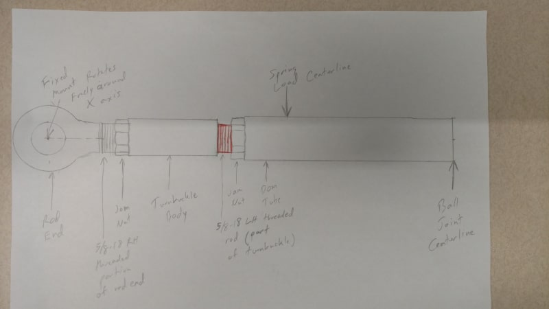
So I made a drawing of the system and I outlined the section in red where I think would be the weak point and the point of failure. It's not going to bend at the rod end shaft since it will rotate...its going to bend at the red section i've outlined.

The drawing shows the exposed threaded sections for nominal length. It will be adjustable in length so the threaded sections can be longer by about 1/4" which will make the system more prone to deflection and bending. Are there any worst case assumptions you might make to model and analyze this easier statically?

5_8ths_UCA_hardware_drawing_dzhug3.jpg


TC
Comm and GPS Systems Engineer
 
actually it will bend everywhere, but it will bend more in the red zone.

I'm surprised the turnbuckle barrel has a jam nut on only one end. What stops it rotating at the other end ? Trivial ... make sure the barrel has flats on it.

For ultimate load I'd stress based on the thread minimum diameter. For fatigue you'd have to consider the Kt at the root of the thread. If you roll the thread (rather than machine cut it) you'll have better fatigue properties.

another day in paradise, or is paradise one day closer ?
 
Your design puts threads within inches of the maximum bending stress. Is this exactly how some aftermarket arms are designed for your, or any application?


I think many, and maybe most rod end mfrs don't include any "sideways" loading of the threaded stud in their load ratings. They really aren't meant for that.
As cool as adjustable control arm length is, I think you'll find that on race cars with adjustable control arms and even passenger cars with adjustable links the spring loads are fed directly into the hub upright via coil-overs or a separate strut.
As others have said, axial only loading. Tension and compression.

At the very least I'd start by only using the threads as close as possible to the fixed mount by eliminating the turnbuckle and lengthening the threaded tube as much as possible. And plan on frequently checking the jam nut for loosening and NDT inspection of the threaded stud .
 
tmoose - I found a similar aftermarket assembly for 1960s Mustangs. Seems like a crazy thing to do.
 
Status
Not open for further replies.

Part and Inventory Search

Sponsor

Back
Top