Continue to Site

Eng-Tips is the largest engineering community on the Internet

Intelligent Work Forums for Engineering Professionals

  • Congratulations waross on being selected by the Eng-Tips community for having the most helpful posts in the forums last week. Way to Go!

Bolt load capacity after tightening 15

Status
Not open for further replies.

Nordic8

Mechanical
Jan 8, 2021
6
Hi all,

I hope its not a stupid question, or if it is then maybe someone can point towards that "simple and obvious" answer that I'm failing to see here! Here goes:

I haven't got much experience with bolted joints, so far simple guidelines such as VDI2230 have helped me out just fine.

However, now I was trying to use VDI2230 for determining the tightening torques for a bolted flange and came across something that I fail to make sense of.

I'll give you a simplified description. It's a pipe with a flange, and an end cap bolted onto it to seal it off. Lets say it has 4 bolts that are evenly spread along the diameter, or 90degrees apart from each other. The holes in the flanges are not threaded, just bolts through and and nuts on the other side.

I'll use the VDI2230 method for calculating these bolts, following the procedure I found in a Würth publication.

Based on the diameter of the pipe and maximum working pressure I have determined that the maximum force on the cap will be 9.2 kN, that makes 2.3 kN per each of the 4 bolts. Therefore the axial operating force Fa = 2.3 kN.

As I have no shear forces to consider, the assembly preload force Fm = Fa = 2.3 kN. This will be my starting point.

Let's say I want to use grade 8.8 bolts. Looking at the VDI2230 table, the next closest load there is 2.5 kN -> size M4 is specified for 8.8 bolts.
Add one step for static concentric load -> 4.0 kN -> M5
Add one step for tightening with a torque wrench -> 6.3 kN -> M6

So the bolts that I need are grade 8.8 size M6.

I will estimate the coefficient of friction to be 0.11. The next closest step in the guidelines I have is 0.10, so lets got with that.

Based on all this, VDI2230 advises me that the tightening torque would be Ma = 9.0 Nm, which would create a 10.4 kN preload force in the bolt. It is said to utilize 90% of the screws yield strength.

Based on my calculation, the breaking load of a M6 8.8 coarse thread bolt at yield strength (640 MPa) is 11.29 kN.
10.4 / 11.29 = 92%, so that's just about right.

But... the assembly is not pressurized when I'm tightening those bolts. By just tightening them, I've already used up 92% of the bolts' reserve, not much left for when I will actually pressurize it.

If i will now calculate how much pressure this assembly can take after tightening the bolts, then I can only use the reserve left in the bolts (8 percent to yield strength) as in my calculation? That's not much...

Or lets give you another really simple example just to illustrate the point I'm trying to make here:
Lets say you have an M6 eye bolt, you insert it through a hole in a rigid steel plate in the ceiling, and screw a nut on the other side. If the nut is not tightened, then you can hang 11.29 kN load on your eye bolt before it breaks, but after you've tightened the nut according to VDI2230, you can only hang 11.29 kN x 8% = 0.9 kN off it before it snaps!.

I'm kinda confused here. What am I missing? All the example calculations I have seen for pressurized flanges, lids, end caps on pressure vessels etc just use the full capacity of the bolts in their strength calculations. But how can I do that if I've already used up 9/10 of it???

Could I tighten the nuts to a lesser torque than specified? But wouldn't the flange then leak, and would the bolts rattle loose / become undone too easily?

Thanks for any feedback (or for proving me stupid, it that happens to be the case :)

J.
 
Replies continue below

Recommended for you

nope ... I meant the literal pubs, rather than the unsatisfying virtual pubs

another day in paradise, or is paradise one day closer ?
 
rb1957 said:
nope ... I meant the literal pubs, rather than the unsatisfying virtual pubs
Well color me jealous, please enjoy a drink for me.

So to answer the previous question - Canada.
 
Here you go the bolt tension increases slightly with the external load applied it doesn’t stay constant as quoted by dauwerda

Quote (desertfox)
No dauwerda the bolt tension won't remain the same.
dauwerda said:
Unless you disagree with my answer above, yes it does remain the same.


quote from one of the site links below:-

Bolt Load vs Applied Load
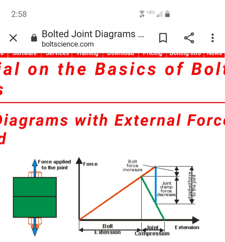
The preload elongates the bolt and compresses the clamped parts. When a tensile load is applied to the joint, some portion of the applied load acts to relieve the compression in the clamped parts and the other portion further elongates the bolt. The portion of the applied load that is carried by the bolt is dependent on the relative stiffness of the bolt and the clamped parts. This relative stiffness is known as the joint constant, C:


The following is a representative diagram of bolt load as a function of the applied joint load:


37811679-971E-4DF9-A3BE-55800C95E12D_nl5mbq.jpg


These are the links I used for the calculations:-


“Do not worry about your problems with mathematics, I assure you mine are far greater.” Albert Einstein
 
I think the doubt still remains and also there is demand for free body diagram.

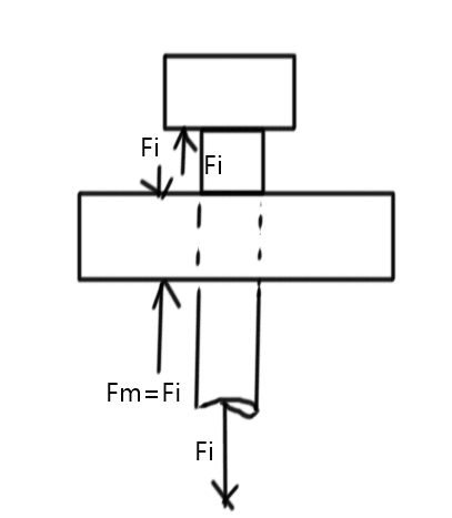
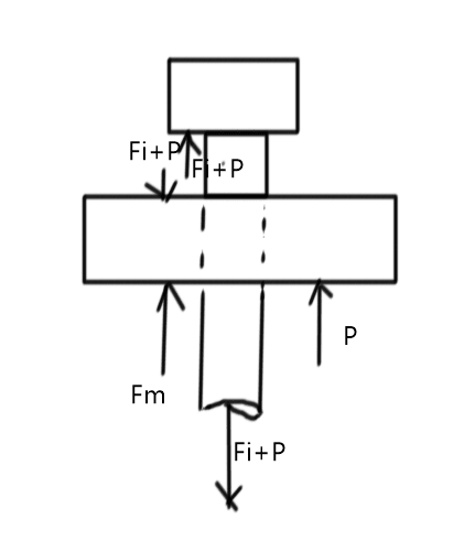
So here are a few FBDs with different scenarios.

1. Only Preload

image_yo4xgj.png

2. With internal load assuming all internal load is taken by bolt (hypothetical)
image_nljrmm.png

image_r4irri.png

So the flange load remains same as for only preload case. But this is impossible as bolt has extended due to extra load and there will be flange gap if the flange does not expand.
3. With load sharing between bolt and flange
image_vemtmf.png

image_cngnt0.png

So the distribution of internal load is nicely defined.
Sorry for long post !


Engineers, think what we have done to the environment !
 
To summarize for the benefit of the OP and I take it now we are all in agreement that the external load applied to the joint is shared between the clamped flanges and the bolt as shown by several posts above.

Both the statments below are incorrect

duwerda said:
That is, as the external force is increased, the clamping force decreases so that the tension in the bolt remains constant.

dauwerda said:
The load is most definitely carried by the bolts, there is no other load path


Take the first quote, if the clamping force decreases and the flanges start to return to there unstressed condition, then the tension in the bolts cannot remain constant because equilibrium will not be maintained, the bolts have to stretch to allow the flange to expand.

in the second statement it says the load is carried by the bolts which appears to conflict with the first statement which states the bolt tension remains constant.


“Do not worry about your problems with mathematics, I assure you mine are far greater.” Albert Einstein
 
Thanks for the great response everyone!

Yeah, I can clearly see where my original logical error was. The theory of how it actually works (which is really clearly explained in the link in desertfox’s original response) does seem counterintuitive at first glance but makes perfect sense when I think about.

Preload and the external load will NOT be added to each other. In a simplified example (not considering joint constant C), preload F minus external load P exuals remaining clamp load.

Preload basically determines how much capacity for an external load there is in a joint before a gap bevelops between joined parts (shortly after which the bolt fails – given that it’s tightened properly and preload value is close to proof load value of the bolt, or 90% of the yield stress)
.
Basically it’s like a credit card – the preload is the credit limit and you can have your card charged for any amount of dollars, as long as that amount is less than the credit limit. Your remaining account balance will be the remaining clamp load.

In a real-life case you would need to consider joint stiffness. Looking at the calculation desertfox did:

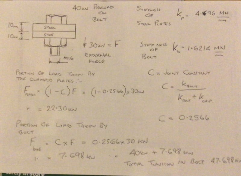
Preload is F = 40kN
External load P = 30kN
Joint constant C = 0.2566

So, when applying 30kN external load to the bolt, the portion of that load that goes into relieving clamp load / pretension will be (1 – 0.2566) * 30kN = 22.302kN

Therefore the remaining clamp load will be 40 – 22.302 = 17.698kN

The remaining part of the external load is 0.2566 * 30kN = 7.698kN, that will go into increasing the tension in the bolt. As a result, the tension in the bolt will be (as desertfox already showed) T = 47.698 kN.

Now, lets assume that the bolt was tightened to approx 90% of the bolt’s yield load. The bolt would then reach it’s yield point at 40kN / 90% = 44.444kN. It means that with 30kN external load applied, this particular bolt would snap as 47.698 > 44.444

Yes, I know that 90% is not a precise figure and in reality there is a lot of variation. But for the sake of argument, lets say that its precise. In that case, the external load capacity of that joint would be (40kN – 44.444kN) / 0.2566 = 17.319kN

When the external load P = 17.319kN, the tension in the bolt T = 44.444kN

So the safe amount external load value (P = 17.319kN) is still far less than pretension. It’s only 43.3% of pretension.

What are the real-life solutions for improving that figure? Using a bit less pretension? Or perhaps spring washers?


Enjoy the pub guys, I’m stuck self isolating for another four days! [upsidedown]
 
Hi Nordic8

You’re welcome.

I will look further into your post in a little while, I’m just doing something at present👍


“Do not worry about your problems with mathematics, I assure you mine are far greater.” Albert Einstein
 
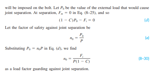
You need to design the bolt properly. Fi is not an arbitrarily high value. It has been provided as a protection against joint separation and hence leakage. Refer excerpts from Shigley.
image_yignqk.png

You need to define a reasonable Po and n_o and calculate Fi accordingly.

Engineers, think what we have done to the environment !
 
I think dauwerda and desertfox are talking the same issue with two different premises, both are true then. While dauwerda considers no-slip condition after locking the preload (plate is very stiff that deflection is negligible), desertfox considers slip will occur due to the difference in flexibility of the bolt and the plate. The bolt internal stress varies as well as the clamping stress, both are reduced after an external load applied to the pre-tensioned bolt. I will try to draw a sketch to demonstrate my thought and come back later.

However, I think the OP made a mistake in saying,
The remaining part of the external load is 0.2566 * 30kN = 7.698kN, that will go into increasing the tension in the bolt. As a result, the tension in the bolt will be (as desertfox already showed) T = 47.698 kN.
IMO, the tension in the bolt shall be 40-7.698=32.302 kN - the external load reduces the bolt pre-tension, not increase.
 
Ok, now I understand one disconnect. I was assuming the stiffness of the flanges was much greater than that of the bolt as alluded to in the second example in the OP. If that is true the increase in the tension of the bolt is negligible (which your equations show). That was never what I was taking issue with however, I'm taking issue with the idea that the bolts aren't transferring the full load of the external load. They are. As Nordic8 summarized nicely, the reason you don't see the tension in the bolt increase equal to the applied load is because as it does increase (at a rate depending on relative stiffness between bolt and flanges), the clamping force decreases. That is, tension in the bolt that had previously been caused by clamping is now being caused by the external load.

I stand by this statement,
Quote (dauwerda)
"The load is most definitely carried by the bolts, there is no other load path."
And everything that has been shown above only reinforces it.
 
you are entitled to your opinion and we can leave it at that however you took issue with the fact that I and several others stated that the external load was shared between the bolt and flange faces and not just the statement in your last post regarding the bolts load path. See all quotes below.

9/01/21 dauwerda said:
If that is true the increase in the tension of the bolt is negligible (which your equations show). That was never what I was taking issue with however, I'm taking issue with the idea that the bolts aren't transferring the full load of the external load

[/quote]8/01/21 dauwerda]No rb1957, we are not saying the same thing. In fact, your first statement, "when the joint is clamped together the external load is shared between the joint faces (compression) and the bolt" is also incorrect.[/quote]

8/01/21 dauwerda said:
The external load applied on the cap is only ever resisted by the bolt tension, there is no sharing this tension with the joint faces.


My issue was you stated the bolt tension remained constant but then stated the bolt took all the load which it clearly doesn't. In fact even your diagram is incorrect because the spring representing the bolt doesn't move until the external force exceeds the preload, the calculation example and the bolt diagram also show that also to be incorrect.
The increased tension in the bolt in the example I posted is almost 20% of the external load I wouldn't call that marginal.


“Do not worry about your problems with mathematics, I assure you mine are far greater.” Albert Einstein
 
Hi Nordic8

Below is an extract from one of the links in my post with the calculations, it shows joint seperation to be a criteria for bolted joint failure and gives a formula for working out the seperation force:-

Joint Separation
The knee in the curve in the bolt load diagram above shows the point where the joint separates. At this point, the applied load is sufficient to separate the parts in the joint (all of the compression in the clamped parts has been relieved), and after this point any load applied to the joint is taken entirely by the bolt. The force that will result in separation of the joint is found by:

Fsep = Fpl/(1-C)

where Fsep = seperation force
Fpl = 90% proof load of fastener


Note that the separation force will always be somewhat higher than the preload force.

Separation of the joint is a failure criteria, and a joint should be designed such that it will not separate during service. The factor of safety on separation is found by:-

FSsep = Fsep/Ftapp where Ftapp is the external force applied to the joint.

The only way to increase joint strength is add more bolts or use bigger bolts either way you have to calculate them.


“Do not worry about your problems with mathematics, I assure you mine are far greater.” Albert Einstein
 
desertfox said:
Note that the separation force will always be somewhat higher than the preload force.

Exact. Before the applied load exceeds the preload, the joint will not move, but the stress on bolt and fittings (plate and nut) is reduced.

In further review, I think it is really depends the manner how the external load is applied. If it is applied directly to the bolt, the bolt will feel 100% of the applied load; if the load is applied through the plate, then the plate will take the force proportional to the relative stiffness of the bolt and the plate. The reason for my conclusion is the fact that the plate is loosely placed over the bolt, the tightening/clamping is done by the nut pushing the plate. After locking, the nut and the plate receive passive force passed by the bolt, which is in an effort to return to the original state, but can't because of the presence of nut and plate. At this stage, the force in the embedded bolt is reversed from tension to compression (tension on the portion inside the nut), which is the so called "preload", or "pre-tension".
 
Hi Nordic8

I found this website which might interest you


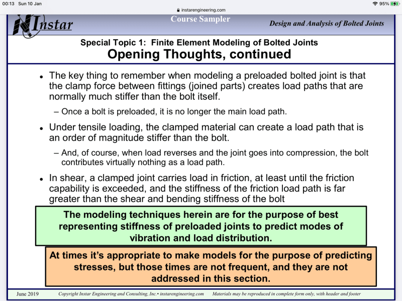
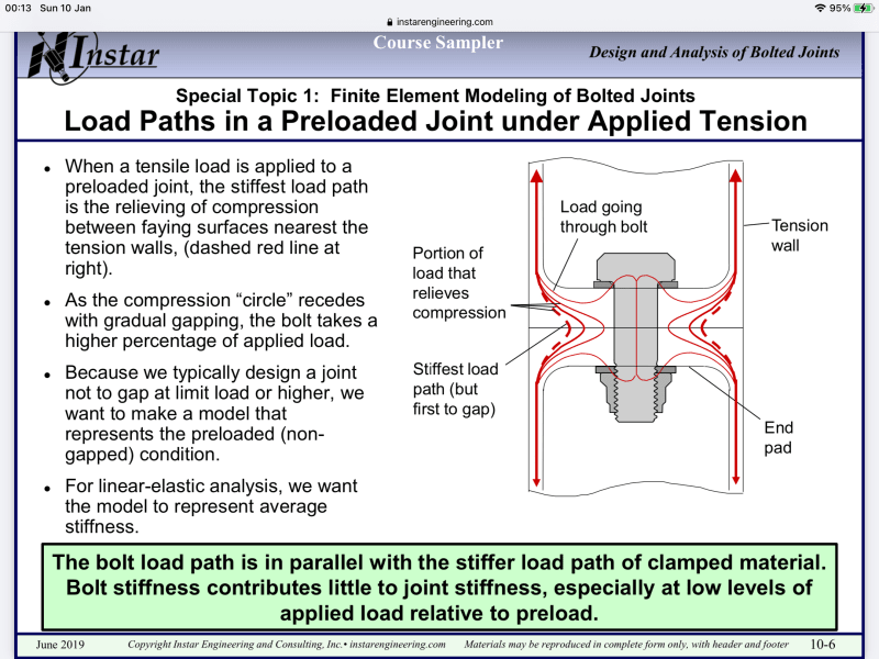
Also I took a snap shot of the last two pages shown below;- it clearly states that once a bolt is preloaded that it is no longer the main load path on the first page and on the second page shows how the major part of the load is transferred through the clamped components, just to clear any further confusion from dauwerda’s incorrect statements.
84B256C5-559E-49D9-9AE5-DF2EE401077A_gozcz4.png


C6BF2C52-F6C4-46DF-B992-D0164A8C2DDE_apt9ha.png


“Do not worry about your problems with mathematics, I assure you mine are far greater.” Albert Einstein
 
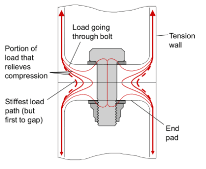
Please note the words "under tensile loading"...and note the load path (thru tension wall) in the sketch. That's exactly I've pointed out - the tension load is applied to parts connected to the clamping plate, not the bolt.

image_oa5rr1.png

image_kak3qc.png
 
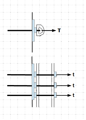
I can think of these two cases below can cause the applied load get directly to the bolt(s). The fittings do not involve in these applications.

image_qq9sxe.png
 
r13 said:
IMO, the tension in the bolt shall be 40-7.698=32.302 kN - the external load reduces the bolt pre-tension, not increase.

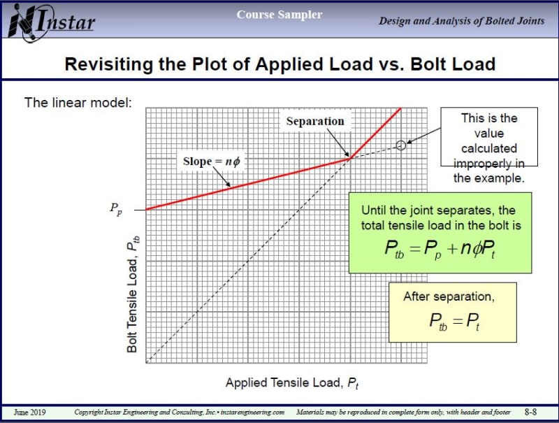
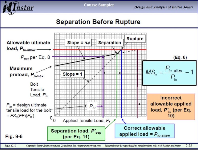
No, I think I got that right. It seems that when external load P is applied, part of it (C * P) goes into relieving clamp force and the rest ((1 - C) * P) will go into increasing the tension in the bolt. This slide from desertfox's link seems to illustrate is as well:

Capture1_o3m2ti.jpg


Capture2_xkeduv.jpg


See how the bolt tensile load keeps creeping up as applied tensile load increases - right up to separation point (or if the bolt reaches the yield point - whichever happens first).

 
It is very interesting, but contrary to my training. I'll keep to investigate, at the meantime, I can give you an example to think about.

Let's compress a spring inside a tube, with force P that cause x amount of shortening, then plug the tube and remove the load, at this stage, what is the force in the spring - compression, or tension? Next, we move the plug back to half of the displacement distance x, what is the force required to move the plug in terms of P, and what is the force in the spring? Note that the case of pretension is just the reverse of this exercise. I could be wrong though.
 
Thanks goutam_freelance and desertfox for those formulas for calculating FOS against joint separation. You've both described the same thing and both of those methods will give the same results.

So, in the example of that bolt with 40 kN pretension and 30 kN external load applied to it:

Separation force (Po, or Fsep) would be Po = Fi / (1 - C) = 40 / (1 - 0.2566) = 53.807 kN
FOS against separation would then be n_o = 53.087 / 30 = 1.794

But how about the capacity of the bolt against yield?

As I calculated earlier, if the bolt is tightened to 90% of it's yield load (as VDI2230 suggests) then the yield point would be reached when external load is 40kN / 90% = 44.444kN

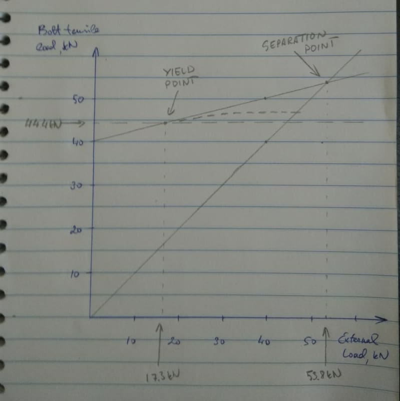
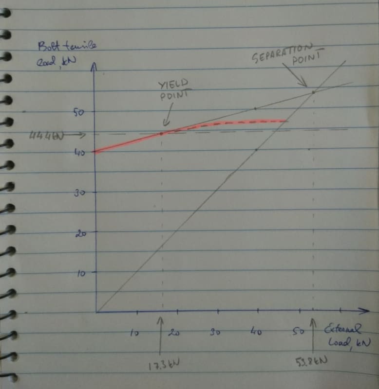
I decided to check how that Applied Load vs Bolt Load graph would look like in this case.

The tension in the bolt equals external load times joint constant: T = P * C. Thats one of the sloped lines on the graph.
The other line is Slope = 1.
The separation point is where those lines cross. The graph seems to confirm my calculations, its somewhere around 53.8 kN
However, the bolt's yield limit is at 44.4 kN... so there's an issue here!

sketch_1v_embqgg.jpg


After the external load has exceeded 44.4 kN, the tension inside the bolt will not grow along that straight line anymore, but instead it will go ductile and would probably be more like the curve that I added to the sketch. There would actually be less than 53.8 kN external load required now to separate the joint.

sketch_2v_lmqvgm.jpg


And my drawing also confirms another one of my earlier calculations - the external load that the bolt can take before hitting the yield point is about P_yield = 17.3 kN.


I'm guessing that the situation on those sample graphs that I posted before is more desireable that the situation that I drew up. You don't want the bolts to reach yield point BEFORE separation point, right?

Or actually - does it really matter? It should be alright as far the external force that the joint has been designed to is less than the for that will get it past the yield point: P_design < P_yield
 
Status
Not open for further replies.

Part and Inventory Search

Sponsor