Continue to Site

Eng-Tips is the largest engineering community on the Internet

Intelligent Work Forums for Engineering Professionals

  • Congratulations KootK on being selected by the Eng-Tips community for having the most helpful posts in the forums last week. Way to Go!

bolt load

Status
Not open for further replies.

212197

Mechanical
Jun 2, 2007
124
Dear Experts,

I have to calculate bolt load of heat exchanger having 3 gaskets.
1 gasket between shell flange & tubesheet & other 2 are in between channel flange & tubesheet.

pl. see the attached detail indicating flange tubesheet configuartion & gaskets.

for circular gasket wm2 = 3.14*b*G*y
gasket has pass partition ribs.

1)While calculating bolt load as per appendix 2 of ASME sec VIII Div1, how to claulate wm2 for gasket having pass partition ribs?
2)whether for calculating total bolt load, Wm2 calculated for all 3 gaskets are to be added?
 
 https://files.engineering.com/getfile.aspx?folder=2eabea9e-20d0-43f7-9d33-308c45d3bbd9&file=Doc1.pdf
Replies continue below

Recommended for you

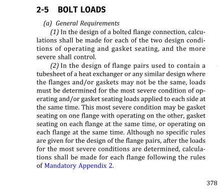
212197, your answers are found in TEMA RCB-11.7 and in Appendix 2-5(a)(2) by way of UHX-4(b).

Briefly, 1) Rib area is added to the area for the ring portion of the gasket. b(rib) x length(rib). b is found per Apx 2, Table 2-5.2. If properties (m,y) are different for the ring and rib, apply each appropriately. Note the rib area shall be accounted for for both operating (Wm1) and seating (Wm2).

2) No, larger values of Wm1 and Wm2 for both flanges in the pair shall be used for further calculations.

Regards,

Mike

The problem with sloppy work is that the supply FAR EXCEEDS the demand
 
SnTMan (Mechanical)
Thanks a lot for your valuable guidance. It helped a lot.

On shell side I have one gasket having no pass partition rib.
On channel side, I have 2 gaskets, one with pass partition ribs & other without pass partition ribs.

I shall calculate bolt load for all the 3 gaskets separately.

I shall have following 2 cases:

1) case 1 : select the larger of following 3 values (a,b,c).
a)shell side bolt load (choose greater of WM1 & WM2)
b) channel side bolt load of gasket with pass partition rib (choose greater of WM1 & WM2)
c) channel side bolt load of gasket without pass partition rib (choose greater of WM1 & WM2)

2) case 2 : select the larger of following 2 values (a,b.3/b.4):
a)shell side bolt load (choose greater of WM1 & WM2)
b.1) channel side bolt load of gasket with pass partition rib (CALCULATE WM1( with p) & CALCULATE WM2(with p))
b.2)channel side bolt load of gasket without pass partition rib(CALCULATE WM1 (without p) & CALCULATE WM2 (without p)
b.3) WM1( with p) + WM1 (without p) = WM1
b.4) WM2( with p) + WM2 (without p) = WM2

question 1)finally I will choose larger of above 2 cases..... is it correct ?

question 2)Am I correct, if I add bolt loads on channel side as it has 2 gaskets?


212197, I don't understand your tubeside configuration, 2 gaskets? Please clarify.

Normally, you would calculate Wm1 for each side (shell, tube), Wm2 for each side. Select higher of the two Wm1 values and higher of the two Wm2 values. Note the selected Wm1 and the selected Wm2 need not be from the same side. Carry out the Apx 2 calculation for each flange using the selected Wm1, Wm2 for both flanges in the pair.

A second, unique gasket on either side would require the calculation of the portion of the load due to the gasket(s) to account for the total gasket area. The portion due to pressure forces may or may not need to modified. This applies to the calculation for Wm1, Wm2 of course contains no pressure term.

Regards,

Mike

The problem with sloppy work is that the supply FAR EXCEEDS the demand
 
SnTMan (Mechanical)

Thanks a lot for your reply.


my configuration is as per attached sketch.

I wanted to know whether I need to add bolt load due to 2 gaskets which are on tube side.
or I should use greater of bolt loads which are calculated for each of these 2 gaskets which are on tube side.
 
 https://files.engineering.com/getfile.aspx?folder=0ee5d8fa-9a70-4ff4-84ee-e682ea700fc6&file=1_Model_(1).pdf
212197, odd arrangement, but why be half-safe :)

Tubeside: Calculation of Wm2 should account for area of both gaskets. Calculation of Wm1 could account for inner gasket only, unless inner gasket is considered to leak. Most conservative to account for both gaskets.

Shellside: Calculate both Wm1 & Wm2 normally.

Regards,

Mike


The problem with sloppy work is that the supply FAR EXCEEDS the demand
 
Weight of channel + product shall be considered.

Regards
 
SnTMan (Mechanical)
Thanks a lot for your valuable guidance. It helped a lot.


r6155 (Mechanical)
I did not get u. can u please elaborate?
 
My mistake was to think as vertical HE, but it is horizontal.
My apologies !!

Regards
 
Just a reminder if it hasn't been covered above.
If shell side & tube side have different pressures:
When designing the girth flanges: you shall transfer the bolt loads from the girth flange which is subject to the highest pressure and gasket seating stresses
to the flange which is subject to the lower pressure and gasket seating stress.

So practice suggests that ideally both flanges shall be of equal size and thickness.
Otherwise when tightening the nuts - the thicker flange might pull the thinner flange and cause leakage in one of the joints.
If you design them identical - they will be equally rigid thus reducing the chance of leakage.

On your sketch - the shellside girth flange looks a bit skinnier.
 
CuMo. Please read ASME VIII Div. 1
When the tubesheet is gasketed between the shell and channel flanges, the shell and channel flange
bolt loads are identical and shall be treated as flange pairs.

Regards
 
r6155 (Mechanical) :

bolt loads not necessarily be identical.Many times shell side & tube side pressures are different. Hence WM1 will be different.
Also, in some cases, tube side has 2 gaskets. Shell side has 1 gasket.
In that case, gasket seating load WM2 will be different for both the cases.
Severe bolt load of all the cases, to be considered.
 
@ 212197

EXAMPLE: channel side 50 bar shell side 2 bar

Do these two flanges have different thickness?. Please, can you explain it?

Regards
 
212197: Thanks
Some quiestion:
1) Is this HE in service or is a new design?
2) Allowable design stress are equal for these 2 flanges?

Regards
 
1) this HE is in service
2) Allowable design stress are equal for these 2 flanges as material of construction & design temp are same.
 
Thanks again. Very interesting.
Now I can`t understand the difference without the calculations of flanges. Can you send it?

Regards
 
Untitled_b9gny1.png


Extract from ASME VIII-1 Mandatory Appendix 2

r6155, the code is very specific about what needs to be done in this case. There is no need to "treat" flanges one way or another.
If his software doesn't cover it automatically (as some don't and others do) he might end up in a very stupid situation.
 
Status
Not open for further replies.

Part and Inventory Search

Sponsor