Eng-Tips is the largest engineering community on the Internet

Intelligent Work Forums for Engineering Professionals

Bolted Cover Plates 6

Status
Not open for further replies.

CDLD

Structural
May 20, 2020
209
1
16
CA
Hello,

We have an existing galvanized beam we are reinforcing partial length with cover plates and we are connecting it with bolts rather than welds.

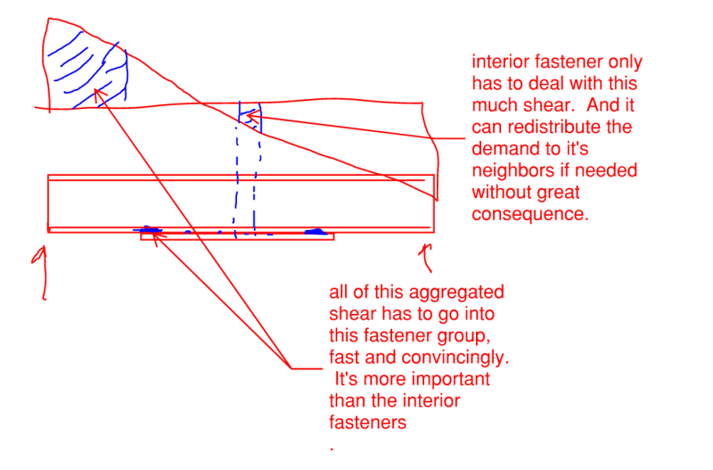
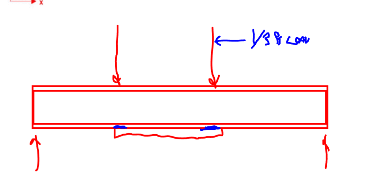
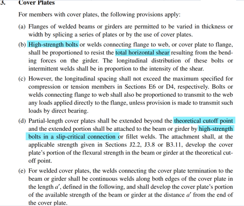
AISC states that slip critical bolts are required to develop the force at the theoretical cutoff points but does not explicitly state SC bolts are required for shear flow.

My interpretation is that slip critical bolts are required at the ends of the cover plate but the interior bolts used for shear flow do not need to be slip critical - Agree?

Screenshot_2024-03-22_100512_qtefyi.png
 
Replies continue below

Recommended for you

Thanks for the replies all.
We have 5 votes for SC bolts throughout and 1 vote for a mixed system - looks like it is Koot versus the world again.

Personally, I am pretty set on SC throughout - I would have a hard time trusting a mixed system without any specific articles or commentary from AISC.

As BA pointed out, the cost saving is not worth the possibility of a screw up.
 
I don't follow. I'm skimming, but I don't quite follow.

A bolted cover plate is atypical, but looks like it's covered in the code. When it's a welded one, the development is at the end, via the end welds and the extension past the theoretical cut off, so the development in a bolted cover plate would be the same thing, would it not?

In the welded case those intermittent welds are prescriptive, aren't they? They don't actually need to transfer any (horizontal) shear force or enforce deflection compatibility between the two pieces because it's a tension force in the plate (bottom flange bending/tension) and it's "fully developed" by the end welds. Why would the bolted case be any different? That speaks to me why the intermittent bolts could be just snug tight. You have to check slip critical bolts for bearing anyway. So slip critical is kind of a "it'll work until it doesn't work" then the bolts go into bearing like a normal snug-tight bolt.

The provisions as written make sense to me. As to what you put on the drawings, well, that's your local standard of care question. Don't slip critical bolts need some kind of special inspection, and even notwithstanding that, if the slip critical bolts are "good" in bearing, if they do slip and or are not appropriately tensioned, surface treatment malfunction, it should still work, at least partially, if not completely with more deflection? We still have that 30" limit on the length of a bolted connection, right?

Last, if nobody mentioned, the bottom flange of the existing beam loses section from the bolt holes.
 
lexpatrie said:
When it's a welded one, the development is at the end, via the end welds and the extension past the theoretical cut off, so the development in a bolted cover plate would be the same thing, would it not?

The development is not just at the end, whether it is welded or bolted. A cover plate has maximum tension/compression at the point of maximum beam moment. Factored tension T[sub]cover[/sub] = phi*As*Fy where As is the area of cover plate. The only way the tension can get from the beam into the cover plate is through either welds or bolts. If the only development is at the ends, the cover plate would have constant tension/compression throughout its length. Clearly, that is not always true. When maximum moment occurs at midspan of cover plate, some weld material or bolts must be located between each end and the maximum force.

Theoretically, the number of bolts required each side of midspan is N = phi*As*Fy/F[sub]bolt[/sub]. Bolts may be spaced in accordance with VQ/I, which means they are not just at each end.

A similar argument can be made for Slip Critical bolts. If there are just enough SC bolts to prevent slip, it cannot be concluded that some of those bolts don't need to be slip critical because they could slip into bearing, contrary to the spirit and intent of the code.
 
I would argue turn of nut is not hard to QC or install for contractors. You need a paint marker to mark the zones, that is all.
It could be argued that it is not as 'accurate' as others. But we had done enough testing and that is why we have the requirements set for the method.
 
I would argue turn of nut is not hard to QC or install for contractors. You need a paint marker to mark the zones, that is all.

It depends on how accessible the bolts are, I suppose. It's not terribly difficult, but it's a multi-step process, so it's relatively slower.

OTOH, twist-offs are a one step process that can be completed by one person, all from the nut side. Inspection can be completed at a distance; the inspector only has to get close enough to see that the splined portion has sheared off.

It could be argued that it is not as 'accurate' as others.

My understanding is that if the proper amount of rotation is specified, turn-of-the-nut, is supposedly the more accurate than twist-offs, at least for uncoated steel assemblies. Not sure if that's true for connecting galvanized plates, though. It's the method we spec for traffic signal poles and high mast light towers.

Direct tension indicators (tension indicating washers) are supposedly the most accurate, since they measure the tension force in the bolt, rather than using torque as a proxy for bolt tension. Checking the old style washers with a feeler gauge can be time consuming, but the newer 'squirters' are easy to verify.
 
The AISC provision states that the termination bolts must be slip critical. But I can't see that it says that the other bolts don't need to be slip critical.
 
Turn of nut can be done with normal HS bolts. You dont need to buy the fancy bolts.
Its rly not thatttt much slower to install, they have snug tighters and then markers after. And from my inspectors point of view it is speedy. You can argue over some number of hours I guess but who cares about that these days.

But I would imagine these tradeoffs make it basically the same price. unless you guys really kill youself over trying to save the client a few thousand dollars. Just remember if you bend now they will constantly ask you to 'bend' later. These free hours to 'make it work' add up.

Not arguing BridgeSmith. It is just what the industry prefers in my area and it seems to work fine.
 

Agreed.. My points are ,

- I just screened some of the responds rather than reading . I looked MANUAL
OF STEEL CONSTRUCTION , LRFD . The same wording ..copy and paste of relevant items;
...
Partial length cover plates shall be extended beyond the theoretical cutoff point
and the extended portion shall be attached to the beam or girder by high-strength
bolts in a slip-critical connection, rivets, or fillet welds. The attachment shall be
adequate, at the applicable design strength given in Sections J2.2, J3.8, or K3
to develop..
...
The longitudinal distribution of these bolts,
rivets, or intermittent welds shall be in proportion to the intensity of the shear.
However, the longitudinal spacing shall not exceed the maximum permitted for
compression or tension members in Section E4 or D2, respectively.
...
IMO, the use of SC bolts at the span will be overkill due to ; the shear force for UDL and shear flow ( q=V*Q/I )for cover plate -flange interface at the span will be minimum which can be tackled with friction and normal bolts.

- I would consider external post tensioning rather than cover plate strengthening .

my opinion only..

...

He is like a man building a house, who dug deep and laid the foundation on the rock. And when the flood arose, the stream beat vehemently against that house, and could not shake it, for it was founded on the rock..

Luke 6:48

 
Turn of nut can be done with normal HS bolts. You dont need to buy the fancy bolts.

Tension controlled (twist-off) bolts are the standard type in my sector, and not much, if any, more expensive than regular HS bolts. It's probably due to scale of the typical installation. A typical bridge superstructure has hundreds, if not thousands, of bolts. We don't tell the contractors what to use. They could standard hex bolts, with turn-of-the-nut or DTIs, but they choose the TC bolts every time.

You can argue over some number of hours I guess but who cares about that these days.

The contractors care. They are acutely aware their man-hours, and labor costs far outweigh material costs in today's economy. Saving fabrication and construction time saves money (compare bridge girders of 40 years ago to today's; you won't typically see any vertical stiffeners in today's girders, where the old ones had hundreds. Today, it's less overall cost to make the web thicker and save all that welding). If they can save time by using more expensive bolts and buying the tool to install them, they'll do it every time.

Again it depends on the number of bolts. The OP's project seems to be in the middle, where any of the methods may be the most cost-effective overall. If possible, I would suggest letting the installer/contractor decide what method to use.
 
Still not following, there's the physics of the situation and then there's code, the two aren't the same creature.

If the ends of the piece are designed for the full (tension) force, the intermittent connections aren't physically necessary, they are in there to satisfy AISC code. It looks like the code is requiring two independent load paths for the same force, which is safe, so to speak, without dealing with how the force actually gets into the cover place in a truly theoretical fashion. If it's just intermittent welds/bolts transferring the force, sure, VQ/Ib and the force is zero at the center and maximum at the end.

Never mind, I think I get it now, the intermittent fasteners transfer the load into the plate, the end fasteners transfer the load out. But.... the zero tension force in the center of the plate isn't a physical necessity.

Ridge-Board-Diagram_1_kc6daj.jpg


Hokie, if the code specifically wanted slip critical bolts on the intermittent bolts along the length, I expect it would say so. They specifically said slip critical at the ends, after all. If that's already a requirement and they meant it to be throughout, they'd have said it, wouldn't they?

You as a designer can provide them, if it makes you uncomfortable from a special inspection standpoint, or as engineering judgement versus the code, but it isn't explicitly required by the text of the code.
 
@Bridgesmith Yes I agree if we are talking about a bridge, with many large girders. This is not that. But could not be a 'small job' either.

I agree, give them the option and let them choose which is best for them. Doesn't matter to me which type they use.
 
Lex,

Or they could have stated that the intermittent bolts did not need to be slip critical. But they didn't. They are discussing the use of bolts and/or welds, and the welds are certainly all slip critical.
 
If the ends of the piece are designed for the full (tension) force, the intermittent connections aren't physically necessary, they are in there to satisfy AISC code.

There will be a number of bolts required for the strength, based on the shear capacity of the bolts or the bearing capacity at the holes. This that number may be more or less than the number required to provide the slip resistance at service load. There's also a requirement for the maximum spacing of bolts along the length of the cover plate to keep the plates together and reduce the potential for rust buildup between the plates (sealing fasteners). Not sure if sealing fasteners are truly needed if the flange and cover plate are galvanized, but I doubt there's an exception (there isn't in AASHTO, as far as I know).
 
lexpatrie said:
If the ends of the piece are designed for the full (tension) force, the intermittent connections aren't physically necessary, they are in there to satisfy AISC code.

While you've gone a bit awry on some of the details, I don't know that the base instinct with that was wrong.

- If you want perfect, composite behavior all of the way along the beam, then you need the intermittent fastening to achieve that.

- If you only had the development fastening at the ends, and no intermittent fastening at all, you'd still have the lion's share of the desired composite behavior in many cases. This becomes more true the shorter that the reinforcement is and less true the closer that it gets to full span. The development fasteners simply do more concentrated work than the intermittent fasteners do.

In this sense, the fasting of the development bolts is a higher stakes thing than is the fastening of the interior bolts. Since it's rational for higher stakes fasteners to get treated more stringently, it seems to me also rational that the development fasteners get treated more stringently than the interior fasteners.
 
I think that is a fundamental misunderstanding of the anchorage force being developed at the ends of the cover plate. You aren't developing the entire force required in the cover plate, you are developing the force that is in the cover plate at the cut off point. The development fastening won't be enough on its own if you want to have the bottom plate behave like a tie for the reinforced member.
 
canwesteng said:
...you are developing the force that is in the cover plate at the cut off point.

Yes, that is precisely the larger, shaded trapezoid in my diagram. Although many engineers do develop the full force required in the plate for good measure.

canwesteng said:
The development fastening won't be enough on its own if you want to have the bottom plate behave like a tie for the reinforced member.

I believe that it will. This simply won't be enough fastening to achieve 100% composite behavior as we normally envision it.
 
Consider the example show below. Here, you would have full composite action, as we normally conceive it, without any interior fastenings. This is because there is no shear, and no increase in moment or flange tension, between the ends of the reinforcement. Where curvature does not change, there is no demand for horizontal shear transfer.

C01_jz7z8x.png
 
Status
Not open for further replies.
Back
Top