I received response from Larry S. Muir. and have pasted it below. I linked the thread; he made many helpful comments.
Colin,
We cannot make design decisions. Ultimately you must use your own judgment.
I have commented below in red:
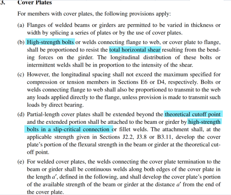
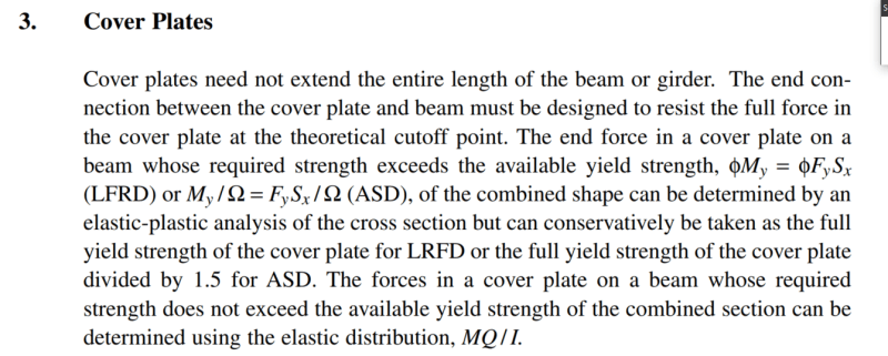
A360-16 section F13-3 states that slip critical bolts are required to develop the force at the theoretical cutoff points but does not explicitly state SC bolts are required for shear flow. My interpretation is that slip critical bolts are required at the ends of the cover plate but the interior bolts used for shear flow do not need to be slip critical - is this correct? [highlight #EF2929]Yes.[/highlight]
I have also posted this question on Engtips:
The overall consensus is that slip critical bolts are required for the anchor force and for shear flow fastening. [highlight #EF2929]Since you have included the link, I have looked at the comments and will provide thoughts relative to some of them. Note that my comments are not definitive and do not reflect the position of the committee or AISC. It may be best to view them as comments from some other random guy.[/highlight]
However, if some of the bolts in the cover plate need to be SC, and they all need to be high strength, there would seem to be little advantage to making only some SC. [highlight #EF2929]I generally agree with this statement. I am usually a big proponent on only using slip critical or pretensioned joints where necessary, but in this case since we are talking about bolts in the same member, I am not sure my typical objections apply, and I can conceive of some benefits to treating all the ‘bolts’ the same. Additionally, the shear flow force will generally be quite small, so going from bearing values to slip critical values is probably not a big deal. There could be specific aspects of your application that would greatly favor the use of slip critical bolts only at the ends.[/highlight]
With only the ends SC, I don't believe you can count on the cover plate to provide additional stiffness for deflection control or any fatigue resistance. [highlight #EF2929]This statement is also true - mostly. F13 does not consider deflection or fatigue.[/highlight]
[highlight #EF2929]If fatigue is a design consideration, which it generally will not be for buildings (though buildings are generally not galvanized either), then the bolts will have to be (at least) pretensioned. Fatigue would be evaluated using Appendix 3 and the physical condition in the structure would have to conform to a condition in Appendix 3 – if you want to keep things simple.
If all the bolts are treated as slip critical, then the joint will be stiffer and the deflection will tend to be less. However, even bolts installed snug tight will produce some preload in joint and will have some resistance to slip. The rigid body slip in standard holes will be small – generally estimated to be half the theoretical clearance and the shear deformation of the elements will also tend to be small. I suspect it is common to neglect these effects when determining deflections and count on the fact that other beneficial effects (partial end fixity) that are also typically neglected will offset the detrimental effects. The choice of slip critical (or not) will change the deflection in the actual structure, but I suspect for many applications the decision will not change things in a critical manner.[/highlight]
There's also the issue of possible installation errors (do you have adequate QC to ensure all the bolts that need to be fully tensioned actually get fully tensioned? [highlight #EF2929]This concern is addressed in Specification Chapter N. There are requirements. Enforcement is an issue that AISC does not and cannot directly affect.[/highlight]
If AISC does intend to say that the bolts for shear flow do not need to be SC, then I believe your statement to be incorrect (at least for the deflection part). if you can count on the plate for strength, you can count on it for deflection. Presumably this is your statement. [highlight #EF2929]This is not correct. Generally, the AISC Specification does not directly address deflections either in terms of determining the deflections that might occur or the limits on deflections. I will provide some examples.[/highlight]
[highlight #EF2929]Commentary to Chapter I provides extensive discussions related to deflections in composite members. The models used to determine strength are not the same models used to estimate deflections. The Commentary to Chapter K states, “The connection capacities calculated in Chapter K are based on strength limit states only. There is no connection deformation limit state considered in these provisions…” AISC Design Guide 36 discusses the ways in which deflections calculated using theoretical models can be adjusted to produce better results. There are other examples that could be given.
The physical deflection that occurs will be different depending on whether slip occurs or not. It is likely not common for engineers to consider this difference and therefore it is commonly not necessary to consider this difference -as evidenced empirically through generally good performance. However, this does not mean the difference does not exist nor that the difference might not be important relative to some application.
I neither want to overstate nor understate the issue.
[/highlight]
I have my doubts about using standard bolts for shear flow and wonder if AISC's statement was in error. [highlight #EF2929]Presumably this is your statement. To my knowledge there is no error, and I see no technical reason to believe there is an error.[/highlight]
To me it doesn't make sense to use slip critical at ends and standard bolts at the interior. I don't understand how the interior bolts would engage if the ends of the plate are restrained from slip; but this seems to be what AISC is saying. [highlight #EF2929]I will start by saying that I think the sort of skepticism you are expressing is good. There are many things in engineering that do not seem to make sense when looked at from one perspective but may make more sense when looked at from other perspectives. To wrap one’s head around a problem it is often useful to apply simplified models, and these simplified models inevitably will be wrong in some manner.[/highlight]
[highlight #EF2929]If the beam and the plate were infinitely stiff and the bolt holes were precisely placed, then preventing relative movement between them and the bolts at the ends would seem to prevent the interior bolts from engaging, but neither of these simplifying assumptions is true. As load is applied the beam flange and the cover plate will elongate or compress independently until the bolts prevent (much of) their relative movement. Additionally, bolt holes are precisely placed. It is generally assumed (based on observations) that about half the bolts in a joint will be installed such that bearing exists before any load is applied. The requirement to only use slip critical bolts at the ends of partial length cover plates is not unique in the Specification. A User Note to Section E6.1 states, “In built-up compression members, such as double-angle struts in trusses, a small relative slip between the elements can significantly reduce the compressive strength of the strut. Therefore, the connection between the elements at the ends of built-up members should be designed to resist slip.” Further discussion is provided in the RCSC Commentary. These are conditions that have been tested. The slip critical end connections do not render the interior bolt ineffective – though I understand that this is a rational conclusion that might flow from some models.[/highlight]
To my way of thinking, the bolts that aren't SC shouldn't be assumed to do anything until the strain in the flange reaches the point where the bolts engage in bearing on the side of the bolt hole, which most of them would, if the beam is stressed to its strength limit state. However, until it reaches that strain level, the beam reacts as if those bolts aren't even there. [highlight #EF2929]I tend to agree with the overall position of this comment, though we might disagree on some of the details. I agree that most of the interior would engage in bearing on the side of the bolt hole. I believe this would happen somewhat sooner than I suspect the commenter does.[/highlight]
[highlight #EF2929]The commenter indicates that there are effects relative to fatigue resistance, deflection, or strength. I agree. However, I think these effects could vary widely in their magnitude. I think the detrimental effect on fatigue resistance would likely be significant and certainly should not be ignored. The effects on deflection would be less (in most cases) and as I indicate above could be offset by other beneficial effects that are commonly neglected. The effects on strength are transitory and in effect do not exist at all once “the [interior] bolts engage in bearing on the side of the bolt hole” which “most [I think all] of them would” at the ultimate condition, and the Specification is largely based on ultimate strengths.
[/highlight]
I also believe SC is for fatigue performance, reduced deflections and resistance to loosening under impacts or vibrations etc. [highlight #EF2929]In this case, as with built-up compression members, I am pretty sure slip critical connections are required to prevent slip where slip will have the greatest detrimental effect. Relative to built-up compression member the Commentary to the RCSC Specification states, “In built-up compression members, such as double-angle struts in trusses, a small relative slip between the elements, especially at the end connections, can increase the effective length of the combined cross-section to that of the individual components and significantly reduce the compressive strength of the strut. Therefore, the connection between the elements at the ends of built-up members should be checked to prevent slip, whether or not a slip-critical joint is required for serviceability. As given by Sherman and Yura (1998), the required slip resistance is 0.08PuLQ/I, where Pu is the axial compressive force in the built-up member, kips; L is the total length of the built-up member, in.; Q is the first moment of area of one component about the axis of buckling of the built-up member, in.3; and I is the moment of inertia of the built-up member about the axis of buckling, in.4.”[/highlight]
[highlight #EF2929]Pretensioning and slip resistance (slip critical joints) also have beneficial effects relative to “fatigue performance, reduced deflections and resistance to loosening under impacts or vibrations”, but these other factors may or may not be critical factors in your design.
[/highlight]
Turn of nut method is pretty typical in my area. I have not seen contractors complain about it. [highlight #EF2929]There is more to providing a slip critical joint than pretensioning, and based on my experience I suspect that not all joints in the commenter’s area are installed in a manner consistent with the requirements of the turn of nut method. However, it is true that bolts are commonly installed with significant preload even when the bolts are permitted to be snug-tight. AISC Design Guide 16 provides some data related to this. Given that shear flow demand is often quite low, this preload may even be enough to prevent slip under service loads, and therefore eliminate serviceability concerns about deflections – though galvanized surfaces may tend to lessen this benefit.[/highlight]
Turn of the nut is probably not as accurate as a direct tension indicator (tension indicating washer). Both can be quite a bit of work for the inspector, unless one of the 'squirter' type DTI's is used. [highlight #EF2929]Though I typically have worked on projects where slip critical joints can be avoided, my preference is to use turn of nut installation. Turn of nut installation tends to result in higher pretensions and I view its complexity as a benefit since I feel like it is taken more seriously when a limited number of joints are singled out for such treatment. I would probably feel differently if I interacted with more bridge construction. It is arguably true that turn of the nut is not as accurate as Direct Tension Indicator Method Pretensioning, but I tend to see this as a potential advantage, not a disadvantage.
Direct Tension Indicator Method Pretensioning is addressed in the RCSC Specification. The RCSC Specification states, “The installer shall verify that the direct tension indicator protrusions have been compressed to a gap that is less than the job inspection gap in more than half of the locations.” While folks may choose to employ 'squirter' type DTIs, they are not recognized by the RCSC Specification.[/highlight]
The twist-off type bolts are easy for both installer and inspector, but requires the specialty tool. If the installer has one, I would not consider changing the contract - just have them tension them all. It won't even slow them down. [highlight #EF2929]This comment probably reflects a gross underestimation of the process required to properly pretension joints. The fact that a gap closes or a spline breaks does not necessarily ensure the joint has been properly installed. If it did there would be no need for statements like “After the snug-tightening operation is performed, the installer shall verify that the direct tension indicator protrusions have not been compressed to a gap that is less than the job inspection gap in half or more of the locations, and if this has occurred, the direct tension indicator shall be removed and replaced” or “After the snug-tightening operation is performed, the installer shall verify that the splined end has not been severed, and if this has occurred, the bolting assembly shall be removed and replaced” in the RCSC Specification.
The statement implies that there are no additional costs associated with requiring all joints to be pretensioned. Many of the inquiries we receive at the Steel Solutions Center involve problems associated with pretensioning. In the most of these cases, the solution is to recognize that the joints never had to be pretensioned in the first place.[/highlight]
The cost saving is not worth the possibility of a screw up. The use of slip critical bolts throughout the length of the cover plate would be a more sensible engineering decision. [highlight #EF2929]Though I am generally a strong advocate for only requiring pretensioning where it is absolutely necessary, this is one condition for which I tend to see some logic in pretensioning all the bolts in the cover plate. There should not be that many bolts and the equipment and personnel will already be at the location. It is a matter of judgment and there could be factors that would cause me to prefer only pretensioning at the ends of the cover plate.[/highlight]
This might be a pretty simplistic and obvious explanation. [highlight #EF2929]The explanation is simple and in some respects wrong, but it nonetheless could be useful.[/highlight] But it is how I like to break things down in my head if I ever end up scratching my head too hard regarding shear flow. [highlight #EF2929]This is a matter of engineering judgment. It is not unusual to employ simple and conservative models in design.[/highlight] O[highlight #EF2929]ften a balance must be struck between “scratching one’s head too hard” and efficiency.[/highlight] I break beams up into trusses. Or in this case break the flange and cover plate up into a truss. I then chase the load paths. [highlight #EF2929]Chasing the load paths is a good approach. In this case if the load paths are chased far enough the interior bolts will go into bearing. Chasing the load paths this far may require more head scratching than some are willing to engage in.
[/highlight]
I don't think that sketch is an accurate representation of shear flow. [highlight #EF2929]No useful model will be accurate. The model proposed is not necessarily bad, but it is not the model I would land on.[/highlight] The question is how much deflection you can live with, without failure. [highlight #EF2929]I think this is definitely one of the questions and perhaps the most important one.[/highlight] I would just email the AISC solutions centre, they are very good about providing answers, but it seems odd that this would be an unintentional mistake. [highlight #EF2929]Sending inquiries to the AISC Steel Solutions Center is always (in my opinion) a good idea, but I am biased. To my knowledge there is no mistake and there are technical reasons to believe there is not a mistake.[/highlight] My conjecture is that at ends of the cover plate (where it is no longer needed), the strains required to engage the bolts would probably cause undesirable deflections and are also less likely to occur before the beam is overloaded - think of a simply supported beam under uniform load, strains are greater at mid span and go to zero at support, so a cover plate at the ends may never be engaged. [highlight #EF2929]I may be misinterpreting the intent, but this description seems backwards to me.[/highlight]
I believe there is a misunderstanding here. From my perspective there absolutely is vertical and horizontal components of resistance being provided by slip critical bolts. The friction from the slip critical nature is a horizontal component and the vertical is provided by bolt tension or direct bearing compression between the plate and the flange. [highlight #EF2929]I am pretty sure that there is no applied tension or compression in the bolts in the model underlying the Specification requirements.[/highlight]
I feel that there is some theoretical justification for mixing bolt types… Whether or not it makes practical / economic sense to mix SC and pre-tensioned bolts when some of the bolts on each beam would need to be inspected and prepped differently anyhow is another matter. That said, if a contractor asked me to consider mixing systems with some real savings up for grabs, I would allow that barring concerns for fatigue etc. [highlight #EF2929]I see merit in these comments and generally agree with them.[/highlight]
For galvanized steel the coefficient of friction should be taken as 0.175, half that of bare steel 0.35. [highlight #EF2929]This position has become controversial in recent years. Above I state, “…though galvanized surfaces may tend to lessen this benefit”. I will admit that my gut (and experience) tells me galvanized surfaces are slipperier than non-galvanized surfaces. However, galvanized surfaces are also softer. It is possible that high pretensions seat the plies deep into the galvanized layer and that this contributes to slip resistance. If the joints are not subject to high preloads from the bolts, then this (assumed/proposed) secondary effect may not exist and slip resistance may be quite small. However, we are not relying on slip resistance at the interior bolts at ultimate loads. Even under service loads the rotation will be larger at the ends where the connections are designed as slip critical and smaller towards the interior.[/highlight]
We have 5 votes for SC bolts throughout and 1 vote for a mixed system - looks like it is Koot versus the world again. [highlight #EF2929]For what it is worth, based on my experience, it is not uncommon to find this sort of distribution. One thing that I think is worthy of note is that while there is a majority opinion, the majority opinion is supported by arguments that in some cases are clearly not acceptable to the majority. This is also not uncommon in my experience. It is also notable that even though ‘Koot’ and I are in the minority, we still tend towards making all the ‘bolts’ slip critical.[/highlight]
I don't follow. I'm skimming, but I don't quite follow… [highlight #EF2929]The argument made here is one I have heard some very smart people make, and it is one I generally accept. If the cover plate is sized for the maximum demand and then the strength of the cover plate is developed at its ends, then this would seem to indicate that the interior bolts do nothing. On the other hand, there is a requirement that “The longitudinal distribution of these bolts or intermittent welds shall be in proportion to the intensity of the shear,” which indicates that the interior bolts do something. The interior bolts cannot simultaneously do nothing and do something, but they can (and likely do) do something somewhere between nothing and something (the something predicated on longitudinal distribution in proportion to the intensity of the shear) and adopting BOTH models in the design process - though in some respects inconsistent with the expected behavior - is not necessarily irrational.
I am now going to go on a bit of a tangent. Steel tends to be pretty ductile. Assuming that all the load is at the ends is consistent with a plastic approach which makes sense for a ductile material. Maintaining longitudinal distribution in proportion to the intensity of the shear is something that would be very important for a brittle material but much less important for a ductile material like steel. Hopefully, it is obvious that there are parallels between the cover plate and a composite beam. However, for a composite beam we adopt neither concentrated demands at the ends nor longitudinal distribution in proportion to the intensity of the shear. Instead, we typically just distribute the shear stubs uniformly. In my mind this tends to be counterintuitive. Concrete tends not to be ductile, and therefore it would seem one would want to be very careful about compatibility between demand and capacity. And… perhaps this intuition is not too far off the mark because now the Specification requires “The effect of ductility (slip capacity) of the shear connection at the interface of the concrete slab and the steel beam shall be considered,” and provides guidance in the Commentary. It has been proposed (as recently as last week’s NASCC) that a way to consider ductility (slip capacity) of the shear connection might be to maintaining longitudinal distribution of shear studs in proportion to the intensity of the shear.
Above I have described three possible models. Echoes of each can be perceived in the discussion you have linked. None of the models are precisely correct. All the models could be useful and could be used to produce safe designs. Some judgment is required. Accommodating the model in which all the demand is at the ends AND the model which requires longitudinal distribution in proportion to the intensity of the shear encompasses both the lower bound and upper bound conditions and therefore seems to be an unassailable approach. Is it overkill? Perhaps, but cover plates are not all that common, so a belt-and-suspenders approach can arguably be tolerated. If you want to use a more rational approach this is possible. Section A1 states, “Where conditions are not covered by this Specification, designs are permitted to be based on tests or analysis, subject to the approval of the authority having jurisdiction (AHJ). Alternative methods of analysis and design are permitted, provided such alternative methods or criteria are acceptable to the AHJ.”[/highlight]
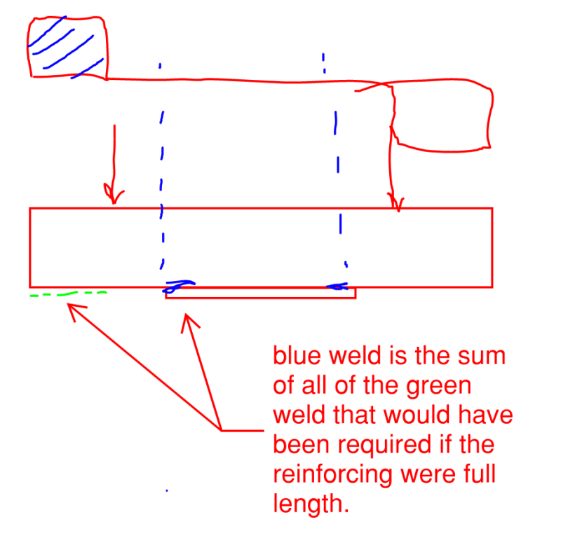
If the only development is at the ends, the cover plate would have constant tension/compression throughout its length. Clearly, that is not always true. [highlight #EF2929]It is correct that “the cover plate would have constant tension/compression throughout its length” if the condition only allows development at the ends. So if the condition only allows development at the ends, it clearly must ALWAYS be true that “the cover plate would have constant tension/compression throughout its length”. It is also true that the model above is inconsistent with the model that predicts VQ/I. BOTH models are rational. BOTH models are accommodated in the Specification provisions. Only the model that predicts VQ/I tends towards the conclusion that the interior bolts must be slip critical (if the end bolts are slip critical).[/highlight]
… contrary to the spirit and intent of the code. [highlight #EF2929]I do not think the use of bearing interior bolts is contrary to the spirit and intent of the code. It is only contrary to strictly elastic models that are commonly taught in engineering courses.[/highlight]
I would argue turn of nut is not hard to QC or install for contractors. You need a paint marker to mark the zones, that is all… It depends on how accessible the bolts are, I suppose. It's not terribly difficult, but it's a multi-step process, so it's relatively slower. [highlight #EF2929]There is also a multi-step process associated with DTIs and the process is described in the RCSC Specification. If the multi-step process described in the RCSC Specification is not followed, then none of the methods should be assumed to produce the desired results.[/highlight]
Inspection can be completed at a distance; the inspector only has to get close enough to see that the splined portion has sheared off. [highlight #EF2929]Chapter N describes Inspection Tasks Prior to, During, and After Bolting. There is more to inspection than is implied by this statement. If the multi-step process described in the RCSC Specification is not followed, then none of the methods should be assumed to produce the desired results.[/highlight]
Direct tension indicators (tension indicating washers) are supposedly the most accurate, since they measure the tension force in the bolt, rather than using torque as a proxy for bolt tension. [highlight #EF2929]Turn of nut installation is based on deformation (elongation) not torque. DTIs do not isolate “tension force in the bolt” due to preload from other potential sources of “tension force in the bolt” unless the multi-step process described in the RCSC Specification is followed. The “tension force in the bolt” is immaterial unless “tension force in the bolt” produces the condition intended.[/highlight]
It looks like the code is requiring two independent load paths for the same force… [highlight #EF2929]I think this is more or less correct. The provisions accommodate two different models.[/highlight]
There's also a requirement for the maximum spacing of bolts along the length of the cover plate to keep the plates together and reduce the potential for rust buildup between the plates (sealing fasteners). [highlight #EF2929]These are also valid considerations.[/highlight]
In this sense, the fast[en]ing of the development bolts is a higher stakes thing than is the fastening of the interior bolts. Since it's rational for higher stakes fasteners to get treated more stringently, it seems to me also rational that the development fasteners get treated more stringently than the interior fasteners… Just to illustrate why the development fasteners are so much more important than the interior fasteners. [highlight #EF2929]I would tend to make these arguments somewhat differently, but they head in the right direction (in my opinion). It is relatively common in structural steel design that when facing conditions that will tend to draw a lot of load to simply assume all the load goes there and then consider the ductility of the less loaded (or unloaded) elements. For the reasons described most of the load will go to the ends, so it arguably is not unreasonable to assume all the load goes there.[/highlight]
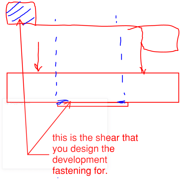
I think that is a fundamental misunderstanding of the anchorage force being developed at the ends of the cover plate. You aren't developing the entire force required in the cover plate, you are developing the force that is in the cover plate at the cut off point. The development fastening won't be enough on its own if you want to have the bottom plate behave like a tie for the reinforced member. [highlight #EF2929]This statement is consistent with the language of the provision, and yes, my ‘BOTH models’ argument is slightly inconsistent with the language of the provision. It can be difficult in these sorts of discussions to keep track of when we are discussing theoretical models and when we are discussing specific language and it can be even more difficult to know how various folks will interpret each. I would argue that even a fundamental misunderstanding can sometimes result in only a small deviation and that is what I think occurs here.[/highlight]
...you are developing the force that is in the cover plate at the cut off point… Yes, that is precisely the larger, shaded trapezoid in my diagram. Although many engineers do develop the full force required in the plate for good measure… The development fastening won't be enough on its own if you want to have the bottom plate behave like a tie for the reinforced member… I believe that it will. This simply won't be enough fastening to achieve 100% composite behavior as we normally envision it. [highlight #EF2929]I think these positions are reasonable. Even a fundamental misunderstanding (or discrepancy) can sometimes result in only a small deviation and that is what I think occurs here.[/highlight]
If you provide the minimum anchorage required by AISC and no intermediate anchorage, for any case with shear (and thus delta in moment, and then delta in curvature), you undersized the reinforcement fastening. I think there are conceivable approaches where you could just fasten the cover plate at the ends and treat it as a tie in tension anchored at the ends, but using the procedure in AISC is not the correct way to design this. [highlight #EF2929]This is true. However, for many common cases the difference will not be important. On the other hand, there could be cases where the difference will be important.[/highlight]
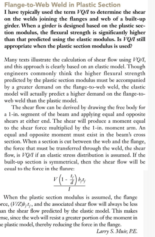
I believe that the opposite is true. A while back, Larry Muir proved to us that using the elastic shear flow formulas produce universally conservative values for situations where the cross section goes plastic. [highlight #EF2929]Perhaps this explains why I am tending to agree with Kooks arguments. I am perhaps (implicitly to this point) biased[/highlight].
Well, I think terminology maybe is a stumbling block - it isn't that shear you are designing for but the moment, but the moment is the shaded area in your sketch (integral of shear diagram). [highlight #EF2929]The shear and the moment are inextricably tied to one another. “Naturally, in some respect these are just two different, but equivalent, tellings of the same story.”[/highlight]
Over the years I've encountered many instances of AISC stating things that were incorrect or poorly coordinated among sections. I assume that this is one of them. So is the subject of this thread quite possible. Ditto for the integral J stuff that we discussed previously. I'm not saying that AISC is doing a bad job. Just that it doesn't make sense for us to take every literal word that they say as gospel. There've been too many inconsistencies for that. [highlight #EF2929]Amen. We do the best we can. I have sat in hours long discussions over words until a committee finally decides that we have the best words only to nearly immediately after publication find that users are interpreting our perfect words in a manner wholly inconsistent with our intent. In some of these cases the interpretations (in retrospect) seem perfectly reasonable. Communication is difficult and inevitably imperfect.[/highlight]
l'll try and send another query to Larry on this topic. [highlight #EF2929]You have. As stated previously, it may be best to view my comments as comments from some other random guy. If at the beginning I had scrolled to the bottom of the discussion, I would have never embarked on this effort. This is a good discussion and lots of people have made good points. For what it is worth, there appears to be no error in the Specification. There are many ways to reconcile the Specification with technical models. It is possible (probable) that different members of the committee had different models in mind.
I think you mention in the discussion that you will share anything you receive back from the Steel Solutions Center. I have no problem with my thoughts being shared. However, over the years I have many times had my comments taken out of context and this tends to lead to problems. What I have presented here is informal and clearly influenced by the trends of the discussion. I am not sure I had anything new to add to the discussion. I am mostly just giving a somewhat different perspective on things that have already been expressed.[/highlight]
I have to dig out that Larry Muir stuff and reconvince myself. [highlight #EF2929]This is the first time that I have heard the position is controversial. I think I wrote the answer about 10 years ago, so things are a bit foggy. I could be wrong, but I would have thought that in 10 years someone else would have more directly challenged my position. I am pretty sure this is a topic that has been discussed by folks who tend to be smarter than me.
Please let me know if you have any further questions.[/highlight]
Larry S. Muir, P.E.
Consultant
American Institute of Steel Construction
866.ASK.AISC
