Continue to Site

Eng-Tips is the largest engineering community on the Internet

Intelligent Work Forums for Engineering Professionals

  • Congratulations IDS on being selected by the Eng-Tips community for having the most helpful posts in the forums last week. Way to Go!

Buckling length for beam hanging from rods 3

Status
Not open for further replies.

novembertango88

Civil/Environmental
Feb 11, 2020
35
Hi all,
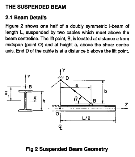
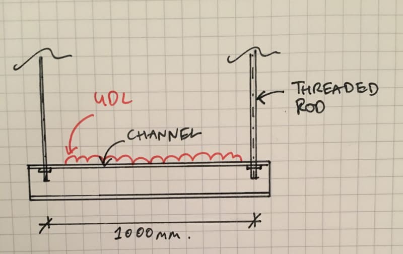
I have a beam hanging from rods as shown in the attached sketch.

What do I take for the buckling length?

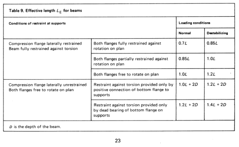
The load is on the top compression flange so I'm considering it destabilizing, the compression flange has no lateral restraint and no torsional restraint. BS 5950-1 table 13 gives a value of 1.4*L(length)+2*D(depth).

Does this sound right?

Thanks, Nick

IMG_2682_nsp31u.jpg
 
Replies continue below

Recommended for you

BA: You took the words right out of my mouth. I must type to slow.

Novembertango88:
From the torsional loading and buckling standpoint, you would be better off if you loaded (supported) the channel beam in the plane of its shear center, which is on the backside of the channel web. The somewhat arbitrary 2.5% number has been around for a long time, and seemed to be a reasonable approx. number when we were designing to allowable stress stds. (allowable stresses based on yield strength of the material). That is a resisting force (bracing force) which seems to take care of (prevent) bucking of most compression elements. MIStructE_IREand… “if P represents the Lateral 2.5% force in the Compression flange required to cause buckling.,” is not a correct interpretation of that bracing force. And, that is particularly true and probably a low number when we are talking about taking the material plastic (beyond yield) in our designs. Of course, if you take a beam like this one beyond yield you will have formed a mechanism and be in trouble anyway. Another possibility for this problem might be to stand a rigid tension element (a sq. stl. tube, or some such) atop the channel flg., and weld it to the channel flg., or to the back of the channel. Extend this up a foot or so, and fix your threaded rod to the top of these tension members. These will impart some righting moments at the ends of the channel if it does try to roll.
 
dhengr said:
BA: You took the words right out of my mouth. I must type to slow.

Sorry dh, I hate when that happens.

Maybe I should have taken more time to read the OP. I missed the fact that the beam was a channel, so I showed an I beam. With that in mind, I think the vertical member at each end should be an angle, attached to the back of the channel with the pin joint above the applied load and aligned over the shear centre of the channel.

Using a member better suited to LTB is not the answer if the hinge point is at or below the load. No matter how stiff the member, the configuration is unstable, so the beam can roll over.

BA
 
Suspending from a higher point would improve stability (see below). I think the beam could be considered torsionally braced.

It really depends on what height we are talking about (at least according to the research I cited above). According to the Dux paper, at least when the cable angle is 90 degrees, the height of attachment would have to be impractically high to get close to the simply supported buckling value.

Apparently (to answer the why of how this happens, as has been raised in this thread)....the height of the attachment makes possible the mechanism for buckling to occur. To quote from the Dux paper:

"If the load attachment point is raised to the shear center axis as well (i.e., 2a2/h = 0), the flexural-torsional buckling strength reduces to zero. This is a consequence of the complete absence of torsional restraint when the beam undergoes displacement u and rotation ø..."

 
WARose said:
"If the load attachment point is raised to the shear center axis as well (i.e., 2a2/h = 0), the flexural-torsional buckling strength reduces to zero. This is a consequence of the complete absence of torsional restraint when the beam undergoes displacement u and rotation ø..."

I couldn't find that quote in the Dux paper, but I suspect a2 is intended to be a1 with a bar over the 'a' (see below). Following the procedure set out in the Dux paper is one option but perhaps not worth the effort for a single beam. Instead, it may be easier to replace the hanger rods with something designed to prevent torsional rotation of the beam.

Dimension a1 in the OP's sketch is less than h/2, clearly not enough, but it isn't clear how much would be enough, so a little conservatism is warranted.

image_xhrtvu.png


BA
 
I couldn't find that quote in the Dux paper....

It's on p.1888. (3rd paragraph)

....but I suspect a2 is intended to be a1 with a bar over the 'a' (see below).

In the Dux paper, a2 is defined as the "distance from shear center to [the underhung] load attachment". Its a1 matches the sketch you posted.
 
The reasons for my reluctance to give high mark on the paper are:

1) Tests only performed on "Aluminum Beams", though similar to mild steel, aluminum's physical properties are quite different.
2) See figure below.

image_rjg92n.png
 
The reasons for my reluctance to give high mark on the paper are....

If you refer to the Dux paper, it is cited in ASME's BTH-1 specification and pretty much every other serious treatment I've seen of suspended beams since. There is no question this buckling can happen.....regardless of material.
 
Failures were cited in the paper provided by HTURKAK, for 30m and beyond precast girders with two lifting points. I think poor construction/erection practice is more to blame though.
 
novembertango88 said:
I've been wondering why it isn't the same as channel supports on hangers typically used for cable ladders but in that case the cable ladder provides lateral restraint to the channel. In this case I don't have that.

If you don't have a ladder, how is the load applied above the beam? If the load is suspended below the beam, it tends to prevent lateral torsional buckling.

BA
 
The beam can buckle like any other channel.

I’m not sure it’s appropriate to apply the normal restraint rules when the beam is a trapeze mechanism with no lateral or torsional resistance.

miestruct said:
If this is a single trapeze set up as below, and if P represents the Lateral 2.5% force in the Compression flange required to cause buckling.. then what resists this horizontal force to cause buckling in the first place?

The 2.5% rule isn’t the value needed to cause buckling, it is the value which is considered to safeguard against buckling. Buckling is spontaneous, due to the internal forces in the beam. The beam needn’t be pushed to buckle. It buckles spontaneously once it’s easier for it to buckle than it is for it to bend.
 
I'd use a channel with its back in the horizontal position, flanges pointing down. Cable loads normally not that great and a little deflection isn't much of a problem for cables as it can be with pipe. Otherwise, cable tray support beams are usually square "tube" shapes.

Reality used to affect the way we thought. Now we somehow believe that what we think affects reality.
 
BS 5950-1 provides a conservative approach for equal flanged rolled sections in Article 4.3.7.7 (see below). Use that with LE of 1.4L + 2D.

image_ysewru.png


image_u4sptl.png


BA
 
HTURKAK said:
The case , 1.4*L(length)+2*D(depth) is valid for partial torsional restraint provided only by pressure of bottom flange onto supports.

Your case ; UDL Destabilising load ( drawn with pink) , since above the shear center of the section .
However, the beam is supported with tension rods. That is, stabilizing effect at supports is provided only with gravity. That is, your case is worse than mentioned case ( which is valid for conditions which some restraint provided at supports).

I will suggest you to use sections not subject to lateral torsional buckling, (i.e. square or rectangular hollow section within the limiting value of LE/ry given in Table 15 .).

I disagree with the bold print. Your case is at least as good as the mentioned case; in fact your case is better than the mentioned case because you are supporting the beam above the shear centre.

I am still not clear on how you are loading the top flange of the channel if you do not have a cable ladder or something similar. One possibility is that the load is hanging from ropes or slings which attach to the top of the channel; that would not be recommended. Another possibility is that the load itself spans from one support to another, for example pipe storage. Please clarify how the load is applied to the top compression flange as stated in your first post.


BA
 
By the way (for anyone who is interested), I had forgot about this (which is embarrassing because it's a thread I started)....in this thread, winelandv was kind enough to post a excerpt from BTH-1 (the 2014 version):


They provide a factor to compensate for the lack of restraint at the ends.
 
Is this a valid restraint model for suspended beam buckling? From David Duerr "Lateral-Torsional Buckling of Suspended I-Shape Lifting Beams"(2016). The C_LTB factor is the BTH-1 factor that WARose linked to.

Suspended_beam_model_swdvsv.png
 
I've performed an analysis on a 24' long wide flange beam, with two lifting schemes as shown. The resulting moments are as indicated. Will they fail?

image_xjolfm.png
 
steveh49 said:
Is this a valid restraint model for suspended beam buckling? From David Duerr "Lateral-Torsional Buckling of Suspended I-Shape Lifting Beams"(2016). The C_LTB factor is the BTH-1 factor that WARose linked to.

And, in case the issue wasn't confusing enough already, see below.


image_pfoebo.png


BA
 
Duerr used the corrected equation.

It is annoying that they didn't correct the equation in the text, given it's an electronic document.
 
With a single channel, there doesn't seem to be any way (short of using a rigid stand-off) to get away from having a torsional moment on it, which will become a bending moment on the support rods. I would want to avoid that loading condition, as it would seem to be a progressive loading situation - the further it twists, the more torsional moment it generates. The exact restraint conditions would be hard to quantify, and therefore the torsional moment magnitude would be subject to significant variation. OTOH, 2 channels back-to-back, with the rods between them, is a balanced and very stable configuration. If necessary, it can also be analyzed as an typically supported I-beam shape, supported from the bottom (presumably, the rod would extend below the channels, with a plate washer for the channels to bear on).

Rod Smith, P.E., The artist formerly known as HotRod10
 
With a double channel supported from the bottom, the support rods must be laterally tied to both channels at the top, meaning that the support rods must resist any eccentric moment in bending.

BA
 
Status
Not open for further replies.

Part and Inventory Search

Sponsor