Continue to Site

Eng-Tips is the largest engineering community on the Internet

Intelligent Work Forums for Engineering Professionals

  • Congratulations IDS on being selected by the Eng-Tips community for having the most helpful posts in the forums last week. Way to Go!

Buckling length for beam hanging from rods 3

Status
Not open for further replies.

novembertango88

Civil/Environmental
Feb 11, 2020
35
Hi all,
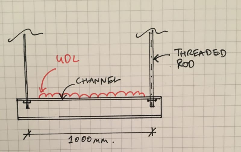
I have a beam hanging from rods as shown in the attached sketch.

What do I take for the buckling length?

The load is on the top compression flange so I'm considering it destabilizing, the compression flange has no lateral restraint and no torsional restraint. BS 5950-1 table 13 gives a value of 1.4*L(length)+2*D(depth).

Does this sound right?

Thanks, Nick
IMG_2682_nsp31u.jpg
 
Replies continue below

Recommended for you

BAretired said:
With a double channel supported from the bottom, the support rods must be laterally tied to both channels at the top, meaning that the support rods must resist any eccentric moment in bending.

Not necessarily. I've seen installations where the channels were tied to each other, but not the support rod. It seems fairly common for suspended walkways. I actually designed a similar system myself, except it was upside down, with the rods holding the beam down (pile testing load frame), but essentially, it functioned the same. The rods go between the channels, but don't actually attach to them at all.

Rod Smith, P.E., The artist formerly known as HotRod10


I just want to remind the sketch provided by OP.
The channel section is supported from top flange by two tension rods , the load is UDL at top flange and the shear center is outside the channel area.

That is, the bottom flanges and bottom flanges are not provided with torsional restraint. However, the top flanges will get limited torsional restraint due to restoring gravity force when the top flange swings. Moreover, the section experience warping torsion due to the eccentricity and flange loading.
Apparently the effective length will be more than the length of the channel .


I proposed the use of square hollow section since , LTB is only possible where the beam has a less stiff minor axis (i.e. Ix > Iy) or , in case of channel ,conservatively 1.5*(1.4*L(length)+2*D(depth)).

You are free to disagree to my respond .I will be happy if you can perform an experiment to see the effective length of suspended channel and share your findings.

 
BridgeSmith,

If the channels are separated with a gap greater than the diameter of the support rod, a keeper plate is required; otherwise the beam is unstable. See below.

image_h9mjig.png


BA
 
HRUTKAK said:
You are free to disagree to my respond .I will be happy if you can perform an experiment to see the effective length of suspended channel and share your findings.

Sorry to disappoint you, but I have no intention of performing an experiment.

I have no objection to using a square hollow section, but BS 5950-1 permits the use of a single channel section. I do not know the theoretical basis for suggesting that Le = 1.4L + 2D but it is included in the code for Destabilizing Load Conditions.

I disagree with your statement "That is, stabilizing effect at supports is provided only with gravity. That is, your case is worse than mentioned case", because a channel, loaded on top and resting on a flat surface offers no greater resistance to torsional rotation than a channel hung from the top flange. However, neither support is particularly good. I would prefer something with a little more resistance to LTB.

It is not clear how the UDL is applied to the top of the channel. It is not supported by a cable tray or ladder, so I'm guessing the load is self spanning between trapezes. If so, the height of the load has an effect on destabilization, but friction between the load and the channel might offer some resistance to overturning. Who knows? The OP is not telling us.

BA
 
BAretired said:
If the channels are separated with a gap greater than the diameter of the support rod, a keeper plate is required;

Agreed, but what would be the purpose of having a gap significantly greater than the rod diameter? Usually, the gap would be about an 1/8" greater than the rod diameter, just to ensure the rod will fit. Plates across between the channels would be required on the top and bottom regardless. The ones on the top don't necessarily need to restrain the rods from movement longitudinal to the channels, though, so support without inducing moment in the rods can achieved fairly easily.

Rod Smith, P.E., The artist formerly known as HotRod10
 
BridgeSmith said:
Agreed, but what would be the purpose of having a gap significantly greater than the rod diameter? Usually, the gap would be about an 1/8" greater than the rod diameter, just to ensure the rod will fit.

There may be no purpose. It could be a mistake in fabrication or the gap was increased to accommodate a larger diameter rod. It doesn't matter; and it isn't worth arguing about. You don't want the rods slopping around in a gap between channels.

BridgeSmith said:
Plates across between the channels would be required on the top and bottom regardless. The ones on the top don't necessarily need to restrain the rods from movement longitudinal to the channels, though, so support without inducing moment in the rods can achieved fairly easily.

Plates would not necessarily be required on the top and bottom. Channel pairs are often separated by vertical plate or channel separators which offer no lateral tie to the rods in question.

Secondly, you cannot avoid inducing moment in the rods if eccentricity is introduced by the applied load. The rods are the only thing available to resist eccentricity.

Personally, I prefer vertical standoffs at each end of the double channels to get the hinge well above the applied load.


BA
 
BAretired said:
You don't want the rods slopping around in a gap between channels.

Agreed.

BAretired said:
Channel pairs are often separated by vertical plate or channel separators which offer no lateral tie to the rods in question.

That makes sense, especially for smaller rods. I was thinking about the one I did, which used 1 3/4" high strength threadbar, so I used transverse plates.

BAretired said:
Secondly, you cannot avoid inducing moment in the rods if eccentricity is introduced by the applied load. The rods are the only thing available to resist eccentricity.

Personally, I prefer vertical standoffs at each end of the double channels to get the hinge well above the applied load.

I'd agree with that, and your solution seems like a good one. It's better to avoid eccentric loading, but if it can't be, it has to be resisted or accommodated somehow.


Rod Smith, P.E., The artist formerly known as HotRod10
 
Status
Not open for further replies.

Part and Inventory Search

Sponsor