Eng-Tips is the largest engineering community on the Internet

Intelligent Work Forums for Engineering Professionals

Bulkhead under vaccum

Status
Not open for further replies.

drodrig

Mechanical
Mar 28, 2013
260
0
0
DE
Hi,

I wrote some time ago asking for and end-cap to close a vacuum volume. I learnt a lot from that post and now I am bringing a similar case.

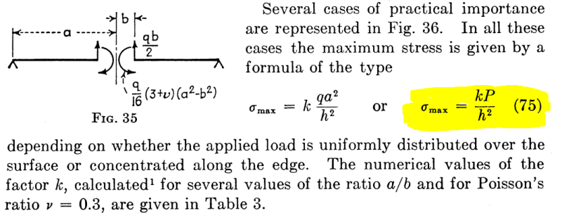
After some calculations I wanted to present the new case here. Checking the results there are some results that make no sense and it is because this formula:

(From the Timoshenko book, Theory of plates and shells)

01b_pizrg3.png


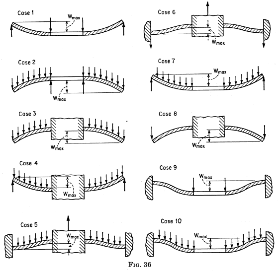
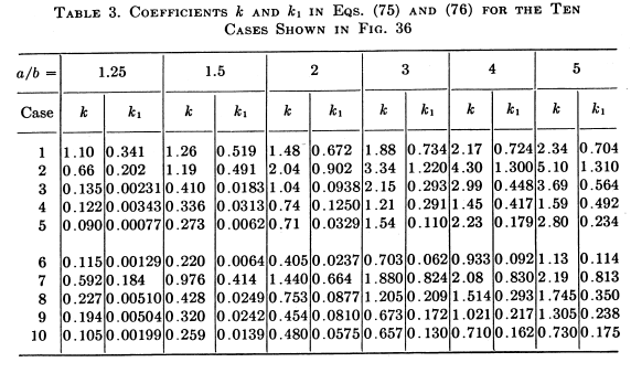
The value of "k" comes from this table and these cases:
("a" is the biggest and "b" the smallest radius of the bulkhead)

02b_ceot7g.png

03b_bcqpjx.png


In the formula, the value of "k" grows when the ratio "a/b" grows. Which means that the maximum stress grows too.

Let's suppose two scenarios of the case 10 (plate clamped in the outer perimeter

Scenario A
Outer radius: 1150mm
Inner radius: 680 mm
ratio a/b: 1.70
value k: 0.365 (case 10, interpolating)
area: 2.7e6 mm2

Scenario B
Outer radius: 680mm
Inner radius: 25 mm
ratio a/b: 27.2
value k: 0.75 (case 10, extrapolating, it is asymptotic)
area: 1.4e6 mm2 (almost half)

How is it possible that the scenario B has higher stress (higher "h" value) when the area is almost half?
Because of the longer (clamped) perimeter of the scenario A?

thanks
regards,
 
Replies continue below

Recommended for you

Hi drodrig

What is “h” defined as? I can see it in the formula and your post but nowhere in the diagrams.

“Do not worry about your problems with mathematics, I assure you mine are far greater.” Albert Einstein


I am not sure why you decided that the scenario B has higher stress..

My points are

- By definiton, ( h ) is plate thickness ,

- q is uniformly distributed load ( refer to fig.34)

- P is the total load applied to the inner boundary of the plate.

- Suggest you to look also ROARK’s Formulas for Stress and Strain ( chp. 11 Circular plates ).

- If you have a software ,in general FEM is the way to go..


Not to know is bad;
not to wish to know is worse.

NIGERIAN PROVERB
 
Here is the definition of "h":
06_waofbo.png


I get to the conclusion of the higher stress if we have the same thickness (h) and pressure (P)

The relation a/b (outer/inner diameter of the bulkhead) and not the absolute dimensions drive the equation.

What about the area? should it play a roll?

cheers,
 
I also checked Roars, but found this nice (easy) equation in the Timoshenko

Next step is running some simulations, but I like first calculating "by hand" to get an idea

thanks


The case 10 is circular plate under the uniformly distributed load , clamped at perimeter and with hole at center . In this case first formula SHALL BE USED..

σ max=(k*q*a^2)/h^2

..And lets check Scenario A
Outer radius: 1150mm
Inner radius: 680 mm
ratio a/b: 1.70
value k: 0.365
area: 2.7e6 mm2
assume UDL q=1.0 mPa , h=20 mm

σ max=0.365*1*1150**2/400 =1206 mPa


And check Scenario B
Outer radius: 680mm
Inner radius: 25 mm
ratio a/b: 27.2
value k: 0.75
area: 1.4e6 mm2

assume again UDL q=1.0 mPa , h=20 mm

σ max=0.75*1*680**2/400 =867 mPa

Apparently the scenario B does not have higher stress ...

Probably it could be better if you post more info. if this is a real case..


Not to know is bad;
not to wish to know is worse.

NIGERIAN PROVERB
 
HTURKAK,

You are absolutely right. I got confused with the capital P (single load) and the pressure.

I'm still puzzled because according to the formulas:
01b_oqeizf.png


P = q*a^2

shouldn't a Pi be included in the formula?

the integrated load (P) should be equal to the pressure (q) times the area (Pi*a^2)

a is the radius

What about the inner radius? is this included in the K value?

I'm fixing my Excel and then I'll present the case I'm working on

thanks
 

Dear drodrig (Mechanical)(OP),

You are in confusion probably for the reason of Figure 35.

- Refer to TABLE 3 again..

- The cases 2,3,4,5,7 and 10 are for uniformly distributed load and the first formula is applicable .( σ max=(k*q*a^2)/h^2

- The cases 1,6,8 and 9 are for concentrated load along the interior edge and the second formula is applicable .( σ max=(k*P)/h^2

- P is concentrated load and the unit is ( say kN ) . If Q is the uniformly distributed load along the inner edge , P =2ΠQ

- Regarding the Fig 35, Refer to Fig. 34, in which the plate is supported along the outer edge and carries a uniformly distributed load. Consider this plate cut by the cylindrical surface of radius b and perpendicular to the plate, you may find that along this section shearing force acting Q = Πqb^2/2Πb = qb/2 and the moment acting will be Mr = (q/16)* (3+ µ){a^2-b^2).

- The values at TABLE 3 are based on Poisson ratio μ = 0.3

I hope this respond answers your question..


Not to know is bad;
not to wish to know is worse.

NIGERIAN PROVERB
 
Now I would like to explain the case I am working on.

We have a chamber which has a section (we call it "insert") that goes inwards. Here an sketch:

21_girb5l.png


I want to calculate the wall thicknesses A, B and C, so we divide the problem in 3 sections to support an overpressure of 3 bars (200 N/m2 pressure difference)

- Starting with A.
It is clamped in the outer perimeter (bolted on a flange). Aluminium 5083 (tensile strength 145 MPa)

a, Outer radius: 1152 mm
b, Inner radius: 680 mm
a/b: 1.69
k: 0.365

04_zjr39z.png


31_urq1tp.png

h, Thickness: (k * q * a^2/sigma)*0.5 = (0.365 * 200,000 N/m2 * 1.152^2 / 145,000,000 N/m2)^0.5 = 25.85mm

So the plate must be at least 25.85 mm. I'll add a safety factor of 3 later.

- For the thickness B. I'll talk later, since there is buckling involved

- For the thickness C, same than A. I assume the outer perimeter clamped (since it will be screwed or welded to the insert-cylinder)
With the new values of k I get a thickness of 21.87 mm

Are these numbers and assumptions right?

I've been playing a bit with xcalcs and I don't get the same numbers

thanks,
 
How much thicker will your flanges at the corners of this be?
If they are not a lot more robust then then will flex considerably and you may need to reevaluate your flexure case.

= = = = = = = = = = = = = = = = = = = =
P.E. Metallurgy, consulting work welcomed


Short answer ;

- PLATE ( C ); Pls look section 16. Uniformly Loaded Circular Plates.

In this case , the edge neither clamped nor simple supported . Take the average of clamped and free case ( relevant formulas ,63 thru 66 and 69,70,71)

- PLATE ( A) ; This is also in-between case and superposition of center loading and uniform loading .

Center loading = ( the load is the reaction of plate C ) Average of case CASE 1 and CASE 6

Uniform loading = Average of case CASE 5 and CASE 7


My opinion..


Not to know is bad;
not to wish to know is worse.

NIGERIAN PROVERB
 
Status
Not open for further replies.
Back
Top