Eng-Tips is the largest engineering community on the Internet

Intelligent Work Forums for Engineering Professionals

Calculate Shear forces on a bolt midspan 1

Status
Not open for further replies.

ochy38

Structural
Aug 18, 2024
10
0
0
US
Im working on a beam problem that has my head spinning. It is an 8' beam with a splice 2' in along the span. The outer beam is a square aluminum tube and the inner sleeve is a solid piece of aluminum. I am trying to figure out the capacities of the bolts, the holes in the sleeve, and the holes in the beam.

Figuring out the stress due to bending at a certain spot along the tube or sleeve is easy enough, σ=My/I. That leaves me with a PSI unit. It's easy enough to convert that to a shear value for the bolt with its area.

Originally, the bolts were horizontal. I was able to easily calculate the stress using the above equation, at the farthest edge of the bolt from centroid, and taking the cross sectional area of material of either the tube or sleeve to determine a shear capacity of that part.

Now, with the bolts vertical, I am somewhat confused on how to find the capacities. It doesnt seem as straight forward as "max stress is this" and "stress acts on this cross sectional area", as the stress isnt a specific value. And what area would it actually act upon?

Appreciate any thoughts! I am aways removed from college and haven't done a problem like this in some time.
 
 https://files.engineering.com/getfile.aspx?folder=19a5adb1-8c73-4430-a4f9-4c7b4a0e86e2&file=beam_example.png
Replies continue below

Recommended for you

The shear force is just be the bending moment at that point divided by the lever arm between the top and bottom interfaces where the bolts act in shear.

Although, depending how long that sleeve is, the whole assembly may well work in bending without considering the bolts at all, but that's another whole load path.
 
By the looks of the sketch it works at least partially via telescoping, with the bolts acting more as locking pins?

In terms of strength, if you want to assume the entire bending force goes via the bolts, the bolt shear capacity multiplied by the section depth simply has to exceed the bending moment. The hole strength likewise.
 
Appreciate the quick response you two! Yes, I know the length of the sleeve is likely adding capacity, but I am being very conservative here.

Lets assume (random numbers for easy math) the sleeve is a 3" solid tube, with 2 1/2" bolts and 1" of hole edge distance.
What area would I use for calculating shear capacity (assuming failure is the bolt shearing thru the edge of the sleeve)? Would it simply be 1/2" (bolt width) times edge distance (1")? Or would I go a different route?
 
Not a simple question. Depends on how big the gap is between the outside and inside parts. If it's small then design for the tube and bar to bear against each other with the bolts just stopping the bar from moving. If the gap is big then the bolts will do something but also bend as well as carry shear. Also have some slop due to oversize holes. The situation with gap isn't a normal detail for moment connections for good reasons.

If you want to calculate it in theory then work out the bending moment. Bolt shear is BM divided by lever arm. Take lever arm = the height of the inner bar less required bearing height which is probably a few mm.
 
the moment is transferred as a couple, shearing the bolts, bearing (area = Dt) in the beams.

of course there are many practical elements to the solution. if it is a very sloppy fit, then the solid splice could easily "clock" inside the tube, and a whole new loadpath becomes active.

And, be the way, I think your solution for horizontal bolts needs further thought. The bending stress does not create the load in the bolts, the moment does. The same thing is happening ... the moment creates a couple between the pairs of bolts.

"Hoffen wir mal, dass alles gut geht !"
General Paulus, Nov 1942, outside Stalingrad after the launch of Operation Uranus.
 
A couple of you had some good ideas with "telescoping". Any good examples on how I would be able to do that? I am unsure on how exactly i'd design an inner sleeve to transfer moment, ignoring "locking pins" (the bolts). I imagine it'd have to be a good long length.

Much appreciated!!
 
Bumping this back up - Can anyone help with some design guidance on even a tight fit tube within another tube designed to transfer moment ignoring the bolts? I have found a handful of posts saying "it should work" like people have done it, but struggling to figure out how to put it on paper.
 
Wouldn’t the bolt shear be the transverse shear force at the intersection of the tube/sleeve? Kind of like the calculation for nail shear on a built up wooden section.
 
Regarding just doing a moment transfer - without positive connection (i.e. a moment splice) I would lean more towards thinking it doesn’t transfer moment and the inner tube would just be transmitting a point load such as a cantilevered load. If it did transfer moment I would think it would be just the simple cantilever reaction force which would be put on the end of the other hollow section. You could also design it as a beam with differing cross sections if it did transfer moment
 
A tube within a tube could be modelled in a similar manner to a pin loaded socket. Moment and lateral loading is modelled as a distributed contact load over the length of the pin inside the socket.
 
Pham - I will look at this a bit more in depth. Looks like pretty good stuff. although it looks like they've broken it down to point loads where the rollers are. Which I'd have to think about a bit more to apply here.

JD - cantilevered load - at the point of the cantilever, wouldn't both shear and moment be zero? I am sort of confused on how i'd work that.

Stress_eng- would that essentially be the same as locating moment, turning into a couple, and using that shear value as acting on a bolt (pin?) or are you envisioning something else? My main problem is I cant get a bolt thru a sleeve (rather, the beam material around the bolt) to have enough shear capacity to resist the moment couple.

Appreciate the thoughts!! Hoping Smoulder, Tomfh, or bugbus may chime in here as well as it sounded like they had at least familiarity with transferring moment to the sleeve based on their earlier responses.
 
For a pin loaded socket, a lateral load is beamed to the centre of the contact length within the socket. The lateral load is evenly distributed over the contact length. For the moment, you can assume a linearly tapering distribution, with peak +ve and -ve distribution values at each end of the contract length (same magnitudes) with zero in the middle, giving the same moment. In some cases, others may assume a sinusoidal distribution, again peaking at the ends of the contact length. Total distribution is the uniform distribution and that used to equate to the moment. Maximum moment and shear seen by pin is located inside the socket. Such loading is dictated more so by joint tolerance. You can control the contact to be over equal short lengths at the two ends of the socket only. The inside is opened up slightly more, so contact cannot occur. The distribution over the shorter length is still assumed to linearly taper. I do suggest doing a web search, I’m sure you could find some useful information.
 
Step 1: Ignore splice and calculate reactions the normal way as if beam is in one piece.

Step 2: Take a free body diagram from one end of beam to middle of splice. Get bending moment and shear force on inner piece.

Step 3: Assume locations of point loads where inner piece bears against outer tube. Calculate these two bearing forces. They won't be equal because the difference between these two bearing forces equals shear force.

Or could assume two distributed bearing forces instead of two point forces.

Step 4: Check inner piece and outer tube for local connection capacity.

Step 5: Check bearing on other side of splice - should be exactly same unless you have something different than the first side checked.
 
Stress-eng- interesting stuff! Thanks for the study. I will definitely dive into it deeper.

Smoulder- thanks for the step by step! Makes a lot of sense. I'll give it a shot.
 
3030_T_slot_properties_RISASection_ouwbhd.png


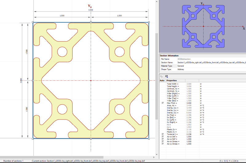
A follow up on this - and this may be a bit of an elementary question. Step 3 in Smoulder's write up-> I can reasonably find the reactions at each end of the sleeve. The point loading has got me tripped up a bit. probably mostly because of the odd shape I'm using as the beam. To determine that the inner sleeve (which sits within the hollow, square-ish section) wont punch thru the t-slot(beam), would that shear capacity simply be based on half of the total cross sectional area (top or bottom based on reaction direction)?. Plus of course necessary adjustments in the code. I am tripping myself up as I can't apply a point load over, say, a bearing pad with known dimensions (a point load has no "length").
 
"I am tripping myself up as I can't apply a point load over, say, a bearing pad with known dimensions (a point load has no "length")." IDU ??

you do your calcs and determine the "point" load on the fastener (and bearing on the plate). this load is carried by such an area ... literally P/A ... no?


"Wir hoffen, dass dieses Mal alles gut gehen wird!"
General Paulus, Nov 1942, outside Stalingrad after the launch of Operation Uranus.
 
I suppose I'm second guessing because its effectively a tube and I'm used to dealing with girders at my 9-5. The bottom half of the cross section as area seems logical to me, as thats what would see a downward force, but I'm just hoping for someone to say "yes dummy", I guess.
 
Status
Not open for further replies.
Back
Top