Continue to Site

Eng-Tips is the largest engineering community on the Internet

Intelligent Work Forums for Engineering Professionals

  • Congratulations waross on being selected by the Eng-Tips community for having the most helpful posts in the forums last week. Way to Go!

Call out for a pattern of concentric holes

Azeemsha

Aerospace
May 2, 2023
9
I am having a pattern of two concentric holes on both the faces of a C channel, these holes are drilled together in one go. The pattern has four sets of these two holes ( total 4x2=8 ). How to properly show this in drawing. I am using iso - gps
 
Replies continue below

Recommended for you

Could you, please provide a "fake" drawing for clarification
Maybe use position with CZ or maybe with SIM......
Or even CZ CZ could be used
 
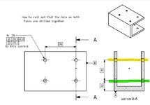
Thanks for your reply, i am attaching a ref drawing. I want to show that each hole of the bolt hole pattern on one face of the C channel and other face is drilled together so that concentricity between the drilled holes are with in a specified tolerance. Hope the question is clear now.
 

Attachments

  • continuous feature clarification.pdf
    34.2 KB · Views: 22
You might be able to use ISO 5458:2018 for reference.
I think SZ CZ or CZ CZ with position could be used.
No need for coaxiality....I think.
 
I would just add a note under the GD&T frame reading "THROUGH 2 WALLS", or something like that.
 
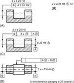
You could use CZ CZ, or sim, or simply treat them as 4 continuous holes with CT and Envelope.( See attached option B) Or a combination of some of these options, it all depends on what function the holes will serve.
 

Attachments

  • IMG_1409.jpeg
    IMG_1409.jpeg
    51.8 KB · Views: 19
QPII - Copy.jpg

So, if E+CT option is used then maybe you can use onlly one CZ in the tolerance indicator
If you don't use E+CT and if you want to link the yellow holes together and then the green holes between themsleves but without "connecting" the yellow pattern with the green patern of holes, then maybe SZ CZ is an option. (However, I do not know it is the best option)

Sometimes I have the tendency to overcomplicate things hence I need help in ISO GPS too.

Anyone with better knowledge ? What are the options here ?
Am I on the right track? Or I am already in the swamp?
 
I like the CT+E notation because it guarantees fitment of a pin between the holes - if that's the design intent. You could get away with a single CZ with an 8x pattern if there's no functional need to guarantee fitment of a pin.

4x / 2x ⌀6 CT (E)
|POS| ⌀0.3 CZ | A | B |
 
View attachment 1085

So, if E+CT option is used then maybe you can use onlly one CZ in the tolerance indicator
If you don't use E+CT and if you want to link the yellow holes together and then the green holes between themsleves but without "connecting" the yellow pattern with the green patern of holes, then maybe SZ CZ is an option. (However, I do not know it is the best option)

Sometimes I have the tendency to overcomplicate things hence I need help in ISO GPS too.

Anyone with better knowledge ? What are the options here ?
Am I on the right track? Or I am already in the swamp?
Haha if you’re in the swamp then I am as well. I agree that both of those options are valid, depending on the function of the part.
One clarification regarding if E CT is the way to go, you would actually say 2x/2x ø6 CT. To indicate that there are 2 groups with two holes in each group that are to be evaluated as one, if that makes sense. Then you would call location ø0.3 CZ to A and B.

The downside to this is that you kind of force to supplier to drill all holes from one side. But if I interpret OP right that is what he wants them to do anyways.

*Edit I missed that there were 8 holes in total, Ryan is correct. 4x/2x is the correct annotation. I just looked at the section view and forget the rest. Long day 😅
 
QFFI - Copy.jpg

So should I understand that shown CZ will link all 4 inside diameters (2 c'bores and 2 thru holes) together and if we would like more "relaxed" specification then we have to use SZ CZ option?
I am asking how would you link only c'bore with its corresponding thru hole and NOT between the patterns (pattern means C'bore+thru hole). Again, using only one tolerance indicator (as shown above) if I add SZ preceding CZ, would that "solve" accordingly per my inquiry above?
 
greenimi, I believe using SZ CZ alone is ambiguous because there's no rule that say's which holes form which pattern. My suggested notation would be:
1732062359703.png

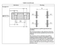
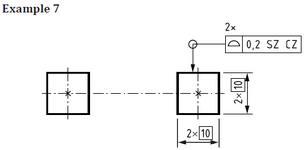
It complies with this clause a(1) of Rule E from ISO 5458:2018 which specifies allowable methods for indicating a multi-level pattern. There are no examples in the standard of this exact method:
1732062421151.png

Here is the closest example from the standard.
1732062947534.png
 
Last edited:

Part and Inventory Search

Sponsor