Continue to Site

Eng-Tips is the largest engineering community on the Internet

Intelligent Work Forums for Engineering Professionals

  • Congratulations KootK on being selected by the Eng-Tips community for having the most helpful posts in the forums last week. Way to Go!

Cantilevered Beam Span NDS 3.2.1

Status
Not open for further replies.

Triangled

Structural
Jun 30, 2013
594
I'm checking some existing glulams, and, ran across the 1986 NDS commentary on 3.2.1 attached, which as far as I can tell, is still appropriate today. I had overlooked this; it is new to me and puzzles me. I ask your help in understanding and appropriately applying.
The key item is definition of "span". I am crystal clear for simple span beam. The questions is how to interpret this for cantilevered beam. For years I have adopted the "knife edge" approach at the continuous support. And I do not really understand how to do it any other way. Below the commentary I have appended an sketch illustrating two optional interpretations (perhaps they are both wrong?). Thank you for your consideration.
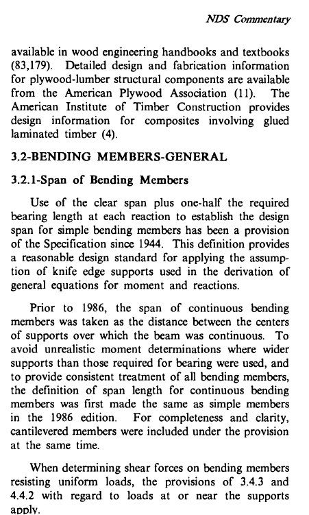
NDS_Commentary_1986_3.2.1_d1s9k6.png


and here is an illustration showing my dilemma
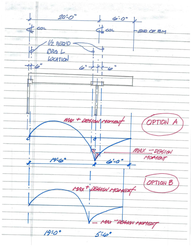
cantilevered_beam_ss6fj3.jpg
 
Replies continue below

Recommended for you

I hadn't really thought about that, either. I think option B is going to be an overly conservative case. The way to go for most new construction would be to assume the middle of the support for span if uplift is restricted. I'd only dip into the savings offered by this (which is in the 2015 NDS - 3.2.1 Span of Bending Members) for retrofits or really unique architectural spaces where you have to design it down to the proverbial gnat's arse to make the signature piece of the architect's vision come to life.

That said, I don't think I agree with A. Here's a sketch - may also be wrong, but hopefully will contribute to the discussion. I think it will vary based on the applied load, the length of the support, and any supplemental connections within the length of that support.

On the left would be a beam that is either restrained from upward deflection between the two assumed knife edges (through connection geometry on top of a post or some other means) or one that has sufficient load to "flatten it out" over the support. Once it's flat, the negative moment can't increase through that distance since any additional load is resisted through bearing across the support.

On the right is a beam that is is not restrained and has a length/UDL ratio such that the beam is allowed to deflect upward between the true bearings.

beam_bearing_dm16vs.png
 
Triangled - I believe there is a more accurate way to model the beam / loading than either Option A or Option B.

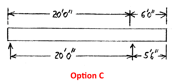
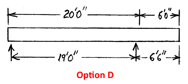
Per my reading of the posted NDS Commentary, the goal is to select the best, most accurate location for a single "knife edge" on the continuous beam support. My proposal:

Option C: Check moment on the "right" side of the continuous beam support.

BeamDiagrams-OpC_600_muj1eg.png


Option D: Check moment on the "left" side of the continuous beam support.

BeamDiagrams-OpD_600_axv71g.png


Select Option C or D that has the lower moment. For this problem the answer will be Option D.

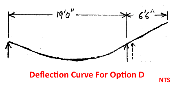
To me, this approach is rational; consider the deflection diagram... the beam tends to load the "left" side of the support.

BeamDiagrams-Deflection-OpD-600_wjyx4b.png


[idea]
 
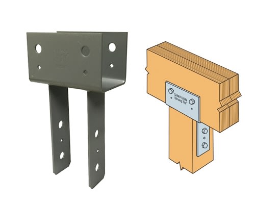
SRE - I like your approach for a bearing only condition. Do you alter your opinion for a beam with uplift restrained?

Edit: I realize the connector shown is fairly short, but figured it would be decent for an illustration of what a longer connection could look like. Also consider a short CMU pier with straps on either side.

simpson_cc44_iwtmoo.jpg
 
That's true.

I would say, though, that doing any of these would require an iterative approach. You have to run an initial analysis to obtain your required bearing area (I'd do a single knife edge and distribute the shear to the reactions), then select the model above (or some other applicable one) that's appropriate for the unique situation. Analyze again, and see if your bearing areas and support location is still valid. Adjust as needed and repeat. Seems like a lot of headache for a wood beam.

 
thank you for your insights.

the job was designed before the introduction of Cv to replace CF and the latest modifications of CL, both of which changes tend to reduce the present day capacity of glulam compared when compared with the era of the original. And, i know in advance that the roof is overloaded. So I am seeking any avenue to mitigate this combined circumstance. My way of calculating moments seems to be definitely conservative to what NDS envisions/allows.

I reached out to the NDS people and received the following reply:
"The NDS doesn’t actually address this in detail so I think this is one of those grey areas where it would be at the discretion of the designing engineer. We don’t have any published examples that detail the process, nor am I aware of any others that broach this specific subject.
Please feel free to let us know if you have additional questions."
Thank you,
Lori Koch, PE
Manager, Educational Outreach
AMERICAN WOOD COUNCIL


I briefly reviewed woodworks software the other day, and, it appears it adjusts design moments based upon this bearing condition; but maybe not. I may try to run a beam and reverse engineer it to see what the logic is. But whatever their interpretation is of 3.2.1, it seems that it may just be their interpretation.

I normally run these kinds of beams in my own spreadsheets and would like to adopt this, IF, i can gain sufficient certainty.

By the way, I will be needing to reinforce some pretty good size glulams overstressed on the order of 20%-30%. Any suggesttion on methods I'd really appreciate.

Thank you.
 
If you really want to dig deeper, then the more appropriate question would be to inquire about the source research for that section. I have noticed the NDS tends to be a little light in directly referencing the research used (as opposed to AISC which is riddled with parenthetical references).

Are your spreadsheets simple formulas or code based? Based on the exchange above, I'd say there'd need to be some relatively complex (for me) logic loops to choose the best model and arrive at the best result.

As for the reinforcement - it may be a thread to itself, but either way post a sketch of the beam and associated framing, etc. There are several options, but they're all limited by space and access (can't bolt on side plates if joists frame into the side, can't bolt on tension reinforcement to the bottom if the ceiling is hard to the bottom, etc.).
 
In terms of reinforcement. Will it be exposed? does it need to be visually appealing?
 
The glulam beams to be reinforced are completely concealed by dropped ceilings with substantial clearance between ceiling and bottom of beam. Therefore visual appeal is not critical.
 
It only fails for negative moment? What about external post tensioning?

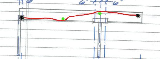
Blue is fixed anchorage, green are items to route the cable, red is the cable.
image_qgxu9l.png
 
I think post tensioning would work quite well.
I feel pretty comfortable working out the forces, but what equipment is best utilized for pulling the cable? Would you have a photo or a spec?
 
Just a turnbuckle would probably do it with the amount of tensioning you would require.
 
Jayrod12,
I was envisioning some sort of calibrated hydraulic device and hoping you might have some recommendation along that line.

Are you envisioning steel cable with turnbuckle? Do you have a recommendation on how to direct a contractor to achieve a prescribed tensile force with a turnbuckle system? Any kind of spec or photo I could review would be appreciated.
 
Triangled - I'll repeat Jayrod12's important question: "It only fails for negative moment?"

For uniform distributed load on full length of the (knife edge simply supported) beam, I believe magnitude of positive moment is much higher (about double) compared to magnitude of negative moment.

[idea]
 
SlideRuleEra and Jayrod12,
I am anticipating a mixed bag of fails based upon a single quick analysis of a simple span, which fails. There are several single- cantilevered cases which I have not run as yet. But I am anticipating these failing in both negative moment and positive moment. Additionally, my sketch, intended to be purely theoretical, shows a cantilever length equal to 30% of backspan,is probably misleading, and I apologize. True beam cantilever lengths appear to be approximately 15% of backspan length. Max backspan length appears to be 60'. I'll have sharper dimensions from the field soon.
I am wondering if my negative moment exaggerated sketch is the reason for your united emphasis on distinguishing between negative moment and positive moment? Is a post tension concept more favorable to the one over the other?
 
phamEng, I should have dimensions soon from the field. For now I know that 1) clearance from TBar ceiling below to bottom of beams is on the order of 10 feet, and, 2) purlins are framed into the side of the beams in 14" deep hangers
 
Triangled - Get accurate details and dimensions on the beam, the supports and loading before proceeding much further. The model used for calculations needs to accurately reflect existing conditions. With a UDL on full length of the beam and overhang that is 15% of the backspan, one thing I can tell you for sure is that negative moment is literally trivial compared to positive moment.

[idea]
 
Status
Not open for further replies.

Part and Inventory Search

Sponsor