Continue to Site

Eng-Tips is the largest engineering community on the Internet

Intelligent Work Forums for Engineering Professionals

  • Congratulations GregLocock on being selected by the Eng-Tips community for having the most helpful posts in the forums last week. Way to Go!

CAST YOUR VOTE! The Great DIY Steel Joist Detailing Competition of 2022 - Win $250 USD 30

Status
Not open for further replies.

KootK

Structural
Oct 16, 2001
18,258
Things have been a little slow around here lately for my liking. In an attempt to liven things up, I'm attempting something experimental: an engineering contest with a cash prize of $150 USD. This is your chance to:

A) Earn yourself some KootBucks and;

B) Establish yourself as a GSEL (Goddam Structural Engineering Legend).

THE CHALLENGE

In the spirit of times, develop a scheme for the fabrication of a steel joist that would be fabricated on site rather than by a conventional joist supplier (Vulcraft, Canam, etc).

THE RULES

1) Include sketches or be forever disparaged.

2) Describe the benefits of your proposal as you see them.

3) Submissions will be accepted until midnight on June 5th, Pacific Time.

4) On June 6th, voting will commence.

5) Voting will close at midnight on June 12th, Pacific Time

5) Votes will be cast by way of members visiting the thread and writing a quick note to indicate their favorite scheme.

6) Votes will NOT be cast by way of giving out little purple stars. Give out all the little purple stars that you wish but none will be recorded as a formal vote.

7) Anyone may enter the contest and win the prize. However, you need to have received at least 9 little purple stars on this forum in the past in order to qualify as a judge and cast a vote that will be counted. I'm setting this restriction only as an attempt to prevent this thing from spiraling into some weird, spammy, cheating affair. Basically, if you're to be in charge of awarding the KootBucks, you need a reputation.

8) The prize will be awarded in the form of an Amazon eGift card. The winner will need to send their burner email address to my burner address or whatever. We're smart kids, we'll figure it out.

9) No prize will be awarded if there are not at least five entries to choose from, including my own.

10) If JAE shows up to judge, he can cast my vote along with his own.

May the best engineer win!

C01_qhq1op.png
 
Replies continue below

Recommended for you

KootK said:
I somewhat rescind that. With the WT setup, I'd actually be fine with single webs hopping back and forth across the WT web. What's a little torsion between friends / panel points...

AISC disagrees, and E5.a in the specification actually calls for the webs to be connected to the same side.

 
KootK said:
1) there was a truss of exactly the kind that you describe.
This makes me smile mostly because of your memory for trusses you've seen. I may have trouble remembering the name of someone I met two months ago at a networking event, but I'll remember the structural system of some building I visited in 1994.
KootK said:
2) Do you intend your truss for larger load applications?
I suppose so, yes. The model I used to size it was one I created to check a 44LH16 that spans 88 feet. (perhaps there will be a thread on that next week as I figure out how to reinforce it)
KootK said:
2a)double webs
my first thought was to consider HSS pieces for the webs because they'd be a stout single piece for compression, but each would have to be slotted at the end. I also briefly thought about whether I'd be okay with webs on one side only if I added horizontal bridging, but I like your idea of alternating pieces...especially in the middle third or so of the span and since the whole thing would need to be flipped over anyway.
KootK said:
2b) Cost of cutting WF into WT
In this exercise, I imagine a situation where the trusses are constructed with some urgency. Otherwise, we'd get in line in Vulcraft's backlog and wait. If this is true, then cost would be less important in the time-cost-quality triangle. The benefit is that work on the truss could be started right away with shapes that are already in the yard. "Don't have a WT5? Fine. Cut a W10 or W12 in half and let's go!"

I recently did a project where trusses would have spanned 50 feet, but the schedule couldn't tolerate the X-month wait, so we dropped a column in the middle. I missed the opportunity to propose the site-built alternative.
KootK said:
2c) on-site jigging
yes, they'd need some wood spacers to square up the chords while the first few webs were put in place.
 
Capture_a6qvq5.jpg

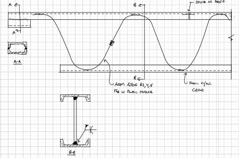
Small C or MC top and bottom chords
ASTM A706 rebar webs prefabricated into common panel lengths (Already getting some rerod for the foundations whats a couple more tons)
Bar Couplers to tie the web panels together, field weld on the bend flats to the C/MC's
Install the C/MC's flanges inward to give a nice flat for roof deck attachment and ceiling finish attachment.
End bearing is created by the formation of a box beam.

Can add additional rebar webs for rooftop equipment on demand.
Use of rebar for the webs keeps the weight down but will need some lateral bracing sim to current joist systems. Can also chop saw down to fit if needed.

I'm making a thing: (It's no Kootware and it will probably break but it's alive!)
 
Celt...not cool. That is exactly what I thought of KootK posted this. (Though I didn't come to the coupler idea - that's a nice touch). Too bad I had 4 dead lines last week and 3 this week...back to the drawing board...

Also, by not cool, I mean I like it.
 
Well, I was going to critique the full pen weld, but it appears that you already adjusted that Celt.

Any idea what kind of truss depths and span lengths you can attain with the r/f rod as your web members?
 
I’ve been meaning to join this discussion but just haven’t had time to do so meaningfully. I work for a steel fabricator and have already given this a lot of thought during the OWSJ shortage. I’ll try to add some more detail and some sketches, but for now here are my general thoughts:
[ul]
[li]Ideally the joist can be fabricated with access to only one side. i.e. only welded on one side of the joist. If you have double angle webs you either need to flip the joist to access the opposite side, or have it raised and welded in the overhead position [/li]
[li]back-to-back members make painting difficult and should be avoided if paint is required[/li]
[li]for those concepts suggesting bolted web members – are you thinking slip-critical connections? I’m asking this because I’d be worried about additional deflection in the joist due to bolt slip. If the bolt holes are oversized by 1/16” both ends, you could end up with a total of 1/16” change in length per web member. If the web member is 24” long that is the equivalent of the web being strained to about 0.26% which could add up over the length of the joist[/li]
[li]having given this a lot of thought in terms of efficiency in fabrication and painting, I’ve come to the conclusion that the ideal joist for this application involves a boat load of eccentricity. I had a concept in mind but haven’t had a chance to explore it in great detail – top and bottom chords made of single angles or WT (single angle preferred), with single angle webs. This makes for easy access for welding (single side only) and painting since there are no hidden surfaces. Fit up of the members would be straight-forward as well. There would be some eccentricity where the webs meet so we can use square cuts have some gap between the angles for weld access. I’m sure this concept makes a lot of engineers uncomfortable. There is eccentricity in the web work points and there is eccentricity in how the axial load from the web is transferred to the chords. The chords are going to do a lot more than just carry axial load and I imagine the deflected shape of this would be pretty funky. This may require a lot of intermediate bracing that would kill the economy of the concept. I was thinking you could play around with different unequal leg angles to reduce some of the eccentricity in the axial load transfer. I’ve only taken this concept as far as some napkin sketches and letting my mind wonder while sitting traffic. My gut feel on this is that you could overcome the eccentricity issues but you’d pay for it in in the weight of the joist. If I had time to explore this in greater detail it may end up being a completely unworkable concept. [/li]
[/ul]

Per Kootk’s opening instructions, I have not provided a sketch – I accept the public shaming that comes with that. Also, throwing out a half-assed concept to a group of engineers is like throwing steak into the lion’s cage – looking forward to the criticism on my concept.

 
adn26 said:
I'm sure your directions/inputs here {and other senior members here} are quit educationally impressive [just add Wacom pen to illustrations]. Also thinking of collecting your feedback in small/large engineering book [Troubles Resolving Key-Textbook]

Ah.. you're alluding to me authoring my own book. Now you're speaking my language! It would truly be a dream come true for me if I could somehow pull together a book that would be read by a meaningful number of engineers. Sadly, it is mostly fear and a lack of confidence that holds me back:

1) I'm not sure that anybody actually reads books nowadays. And that may be even more true in 2050 when I retire and might finally get a potential book written.

2) I'm intimidated by the publishing process as it would pertain to someone with no discernable credibility. As you know, most structural engineering books are written by professors. I imagine myself marching into a publisher's office and arguing "...but, but... I harbor a number of strongly held fringe opinions that at least five people care about in cyberspace?!?".
 
adn26 said:
then extend the time limit

This may be a good idea and, obviously, is something that I could do without risking divorce. This got off to a slow start but does seem to be picking up a bit now. If a few people tell me that another week would be a welcome extension, I'll update the rules to facilitate that.
 
The use of channel sections is interesting, but your size options is a tad limited in the small sections. One could come up with a flexible design for sure. Assuming one sets up a jig on site to build many of these, your welds are not as nice given the channel flanges. Flipping the joist to weld both sides will slow things down a tad to. I had not thought of a C section for the chords.
 
Brad805 said:
Old school joists used a lot of pre-bent rods to speed things up. Those could be produced in various geometries in lengths of say 6'-0" or so for easy handling on site.

This drifts a bit from my original intent (not expressed) in a way that I didn't anticipate at the beginning: significant partial prefabrication. To utilize pre-bent rods in a way that would be cost effective, I would think that you'd need to have a third party mass producing those and set up as, effectively, as a somewhat traditional "supplier" of those components. I'm fine with that as as far as the parameters of this contest goes. At the same time, however, I will consider the need for partial prefabrication to be a minor "con" when it comes to casting my own vote. You know, unless someone can convince me that bent rods can be made by some guy in his back yard rolling them through a tire rim mounted on a lathe or something. I've actually seen that for wood joist fabrication. You know... Alberta.
 
I submit for consideration the chain link fence of steel joists. Not sure what kind of capacity you would get out of this thing, but it should be simple enough to build(?)

Screenshot_2022-06-02_115119_d7e7yo.png
 
Brad805 said:
Presumably, the winning solution is aimed more at being practical and not the lightest.

Yes. In my view, the winning entry will, in large measure, simply be that which is most cost effective. In the event of a tie, other factors such as engineering awesomeness might factor in meaningfully. Things like constant shear capacity, robustness of seat, general elegance etc. So it is certainly not the case that the lightest entry wins. That said, I do feel that the weight of the joists will factor in significantly in ways that other than just the anticipated procurement cost of the constituent materials:

1) Shipping costs.

2) Craning & handling costs on site.

3) Handling costs at the point of fabrication (CANPRO's flipping concern among other thing.

An additional concern with respect to shipping, I feel, is the potential for any joist configuration to "nest" well for shipping purposes. It is my understanding that this is actually the main reason that stiffening joist seats for rollover breaks the bank.

 
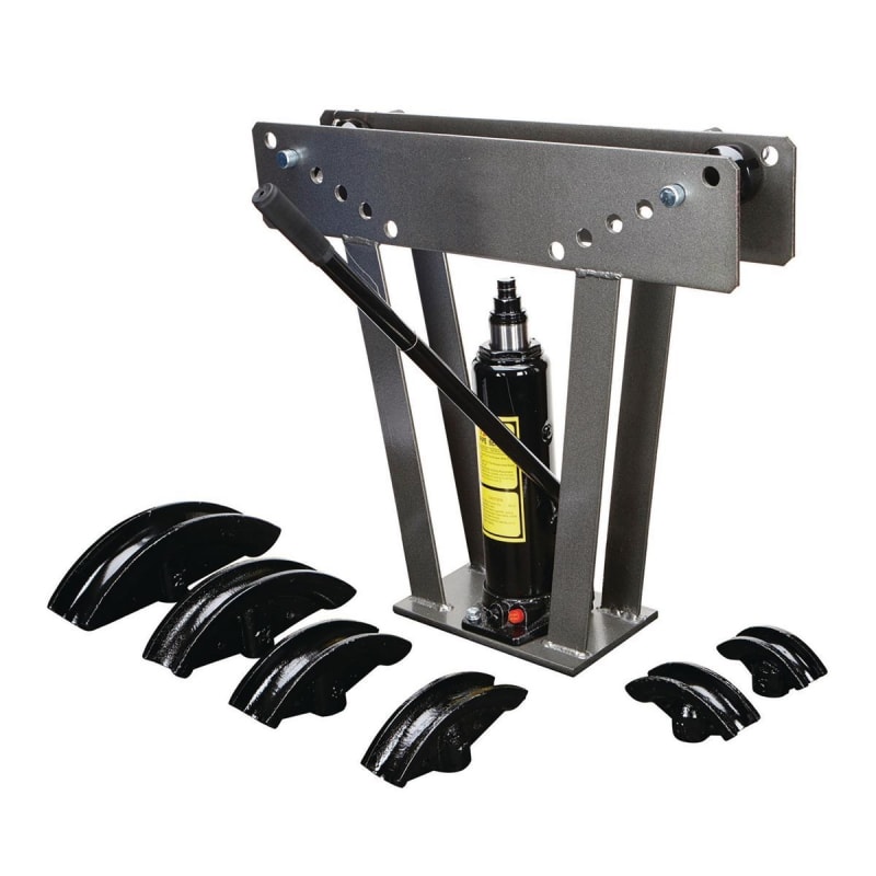
Should be able to bend #3-5 bar using one of these from Harbor Freight, so pre-fab panels an option or send it out in sticks: Link
32888_W3_qvi4if.jpg


I'm making a thing: (It's no Kootware and it will probably break but it's alive!)
 
@winelandv:
super quick and dirty model with C3x5 chords and #4 web bars - 30 ft long. 24" total depth appears to be deflection limited for L/240 at 200 plf superimposed.
Capture_q56awh.jpg


I'm making a thing: (It's no Kootware and it will probably break but it's alive!)
 
I agree with CANPRO re: crane time. It sounds like it's not a big deal (just flip it over dummy) but it can add up to a lot. Not least of which is because it takes the crane away from other work items in the shop. Most places don't have enough overhead cranes to go around so anything you can do to minimize the number of flips is highly desirable.

BTW for those looking at more typical type joists: attached is a report on OWSJ failures (Robb Engineering / Dominion Bridge Company) for joists produced between 1963 and 1985. Typical large joist supplier configuration (round/bent chords in-between two angles). Lots of weld failures / QC issues / etc but I would submit those failures primarily occurred because the nature of welding the webs to the chords is tough for an average welder. It's a small opening with a short weld length that doesn't allow a lot of flexibility to screw up the start (which is often the case). I would not want a regular / misc steel fabricator who doesn't do these everyday to perform that weld. Regular fillets or grooves or whatever in typical setups are 100% the way to go. To be clear it's not that they can't be performed well. They obviously can be. But I think you are likely to have a far greater number of QC issues with those types of non-ordinary welds (non-ordinary for those performing them) that should factor in as a con when we are assessing.

I'm partial to kipfoot's design and had something along those lines planned. But I feel it would be poor form to submit a similar design with only minor modifications. So I'm still at the percolating stage.

 
 https://files.engineering.com/getfile.aspx?folder=4e15671a-aefe-45a9-baca-10b9f74b41ee&file=OWSJ_Failure.pdf
Enable, you beat me to the Robb joist reference...I was circling back to post that when I saw the round bar proposal. This is in my neck of the woods and I've been fortunate (??) enough to have been involved in some Robb joist inspections and have actually seen a Robb joist unzipper its webs under heavy snow - scary stuff to say the least. Not to say Celt83's concept won't work, it is dead simple which I like, but the flare bevel welds on the rods just remind me too much of the Robb Joist situation.
 
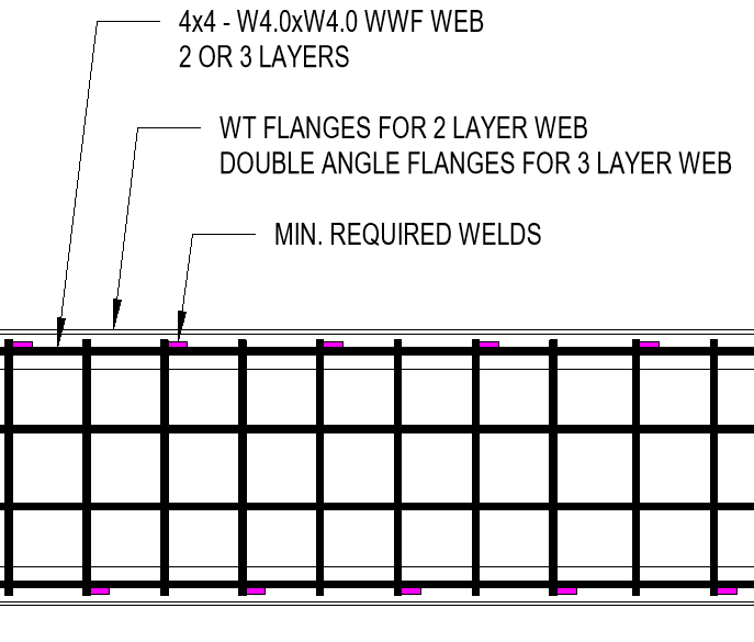
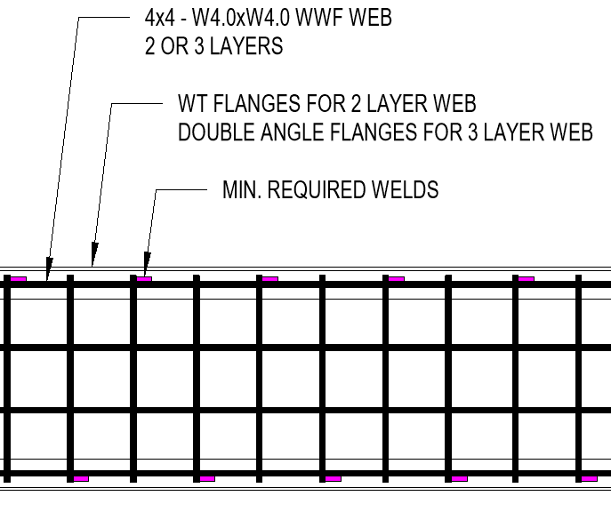
@Bones206: I gotta call you out on this one. You're basically asking for two way Vierendeel action out of that WWF, right? Maybe if you turned the mesh 45 deg.

You get bonus points for May for nailing the Tie-rod through trench solution for SteelPE.

c02_dqvb8b.png
 
Celt -

I'm glad I'm not the only one who keeps thinking of the old "Erector Set" toys we used to play with.

Idea #1
My mind keeps returning to the idea of having Chords with pre-drilled holes. They would ship with all the diagonals already connected via a single bolt to each chords. As such, they could be "collapsed" for shipping and erection. Using the same member sizes all over the place for easy erection / construction.

Then the field would have to add in the verticals for stability to finalize them. Probably easiest to do with wood... just because you could nail in the verticals though the chords would be marked where the verticals are expected so that the you don't have to have quite as many pre-drilled hole locations. But, it could still work for steel.

The main problem I see is that steel joists (and wood joists) are so efficiently built these days that it would be tough to make this more economical.

Idea #2
My mind also keeps returning to the idea of using HSS tubes instead of WT's and Single angles and such. I know they're currently more expensive, but they also make really good trusses. Plus, architects and owners love the look. Maybe they'd be less prone to construction damage or erection accidents too.

It would be a somewhat different application (i.e. more architectural importance), so there may not be nearly as much demand.

Regardless, we'd just have to come up with a way to make the connections easy to mass produce. But, that's a thought for another post.
 
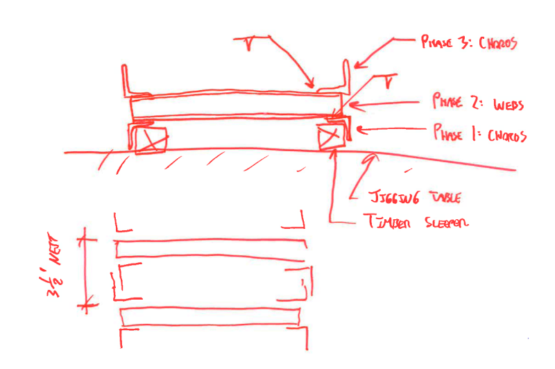
Since we're getting into the weeds on how to actually fabricate these things, this is what I had in mind:

1) No flipping but, then, different welds on the two sides of the webs.

2) A 3.5" +/- nesting width.

C01_xfejff.png
 
Celt83 said:
Should be able to bend #3-5 bar using one of these from Harbor Freight, so pre-fab panels an option or send it out in sticks: Link

Nice...

To play Devil's advocate, once you go down the bent bar path, are you not obligated to perform some testing prior to implementation?
 
Status
Not open for further replies.

Part and Inventory Search

Sponsor