Continue to Site

Eng-Tips is the largest engineering community on the Internet

Intelligent Work Forums for Engineering Professionals

  • Congratulations KootK on being selected by the Eng-Tips community for having the most helpful posts in the forums last week. Way to Go!

CAST YOUR VOTE! The Great DIY Steel Joist Detailing Competition of 2022 - Win $250 USD 30

Status
Not open for further replies.

KootK

Structural
Oct 16, 2001
18,085
Things have been a little slow around here lately for my liking. In an attempt to liven things up, I'm attempting something experimental: an engineering contest with a cash prize of $150 USD. This is your chance to:

A) Earn yourself some KootBucks and;

B) Establish yourself as a GSEL (Goddam Structural Engineering Legend).

THE CHALLENGE

In the spirit of times, develop a scheme for the fabrication of a steel joist that would be fabricated on site rather than by a conventional joist supplier (Vulcraft, Canam, etc).

THE RULES

1) Include sketches or be forever disparaged.

2) Describe the benefits of your proposal as you see them.

3) Submissions will be accepted until midnight on June 5th, Pacific Time.

4) On June 6th, voting will commence.

5) Voting will close at midnight on June 12th, Pacific Time

5) Votes will be cast by way of members visiting the thread and writing a quick note to indicate their favorite scheme.

6) Votes will NOT be cast by way of giving out little purple stars. Give out all the little purple stars that you wish but none will be recorded as a formal vote.

7) Anyone may enter the contest and win the prize. However, you need to have received at least 9 little purple stars on this forum in the past in order to qualify as a judge and cast a vote that will be counted. I'm setting this restriction only as an attempt to prevent this thing from spiraling into some weird, spammy, cheating affair. Basically, if you're to be in charge of awarding the KootBucks, you need a reputation.

8) The prize will be awarded in the form of an Amazon eGift card. The winner will need to send their burner email address to my burner address or whatever. We're smart kids, we'll figure it out.

9) No prize will be awarded if there are not at least five entries to choose from, including my own.

10) If JAE shows up to judge, he can cast my vote along with his own.

May the best engineer win!

C01_qhq1op.png
 
Replies continue below

Recommended for you

dold said:
Design fastening (PAFs) based on shear flow demand plus vertical/direct gravity demand? Heavier fastening towards the ends of the joist. Probably be best to have end diagonals to form a closed "megapanel".

Me thinks spot welds would be a more reliable fastening system with higher capacity likely.
 
The cold formed joist proposed by milkshakelake is great. The idea of cold formed trusses aren't new, just putting the same concept in a different application.

Using sheets of deck as your web is very clever and simple. I think I'd want some sort of testing to back up the design of this - no specific reason off the top of my head, just a gut feel.

kipfoot, I love a good hand sketch...your last post with the angle cope is a great one. You could go with an unequal leg angle and reduce that eccentricity further, but that might put you into an odd-ball angle size that isn't readily available.
 
Koot said:
It seems to me that you'd need both a diagonal and a vertical at the end lest the truss itself kick a large diagonal point load into the decking. It's an interesting mechanical problem.

Concur. I can see a lot of (perhaps not-so-wasted) hours spent risa 3d'ing this thing. More as a thinking/visualization tool as opposed to a hard numbers tool in this case. And I bet some of the principles used in diaphragm design could be useful, but this is a much smaller component-level analysis so maybe not so much...

buncha folks said:
Koot: Ultimately, I suspect that the biggest armor chink for both this and Bone's concept would just be difficulty in running services through the joists.

Lo: Much worse than your traditional sawzall hole through a wooden I-joist? I'd think the WWF would be easy to cut and reinforce (for services over 4"), and while the decking might require a reinforcement panel surrounding the opening.. still doesn't feel that onerous.

milkshake: You could feasibly run pipes through it with some angle reinforcement. It reminds me of repurposing old shipping containers for homes and such.

I thought about that when considering how bridging would be installed. Smallish holes ~2" diam would probably fly without much reinforcing. Anything bigger and I think doubling the deck would be ideal. But that wouldnt work for anything over ~~1/3 joist depth - totally shooting from the hip on that number. Then you'd be looking at angle reinforcing. @milkshake - ditto on the shipping container thing. From what I've heard, dealing with those things is/can be a real headache.

Lo said:
Edit: How thick is "roof decking" in your part of the world? I'm thinking of our 0.35mm stuff, but yours is likely thicker.

Typically 22ga on the east coast of the US. 20ga is pretty common out west for various reasons. On that topic though, I think a bit of consideration would be given to the deck profile selected, of course. Part of me thinks that a slim profie 9/16" form deck (type C) would be more suitable than a bigger 1.5" B deck as I had originally thought of. We don't have to span for out of plane loads. And IIRC you get better shear values out of the lower profile decks. And it just feels more correct to have the "line of action" / centroid of the deck closer to the centerline of the joist...instead of having in plane shears wandering all over the place. I've got nothing to back up that feeling though. Plus it would give opportunity for more frequent fastening. Those are normally spec'd at a lighter gauge - 26ga is pretty common for 9/16" C deck.

But...i'd have to look and see but thinner decks might not have interlocking sidelaps so the only option for fastening sidelaps would be screws. Punched sidelaps (deltagrip, etc) are a lotttt faster to install. Ideally we'd be able to just plop down a single 36" wide deck module along the entire length of the joist - flutes parallel to the chords - and forget about sidelaps, but then we lose all (some? most? not so much?) vertical capacity, accordion style.

XR250 said:
Me thinks spot welds would be a more reliable fastening system with higher capacity likely.

I can see it both ways. There are so many variables when looking at the capacities. PAFs are pretty stout. But only as good as the install. I've always preferred PAFs for use on bar joists. I've seen so many joist top chords totally melted/destroyed by sloppy deck welding. But welding to the stem of a WT the welders can just go to town on it.

CANPRO said:
I think I'd want some sort of testing to back up the design of this - no specific reason off the top of my head, just a gut feel.

You and me both. And probably everyone else. Maybe the KootFund will be able to finance an ESR report.

 
Brad805 said:
Notes:
1. Too heavy still.
2. Parts simple, and a jig would be easy to make.
3. Welds seem too light.
4. This is one of the lightest WT sections.

First, whatever system/software you're using is pretty dang cool. Also:
1. I think it's better suited to longer spans. I tried a 40' truss, 30" deep and it's around 15 lb/ft.
2. I'll take it.
3. If the webs are at a steeper angle, there's more linear inches for weld each side of the web, especially with a deeper WT
4. I like a WT4. I tried a WT4x6.5 top chord with a WT4x5 bottom chord. Equiv to a WT 2x6.5, but with more flange for welding.
kootktruss_nmesyu.jpg
 
Great discussion.

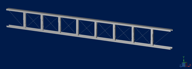
I'll throw one into the ring, tension only diagonals, maybe steel cables.
tension_only_iwbrpf.png


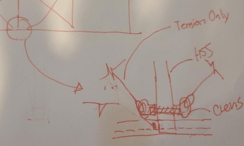
Top and bottom chords be a channel type shape like in Celt's example and the vertical member I was envisioning a vertical angle or HSS tube with some clevis type attachments for the cables.
truss_sjso41.png


connection_uf0oj1.png


S&T -
 
Hmm, two concerns to be mitigated with that one S&T -- I think you would end up fighting stretch in the cables (presumably new/unloaded) and in the connections (including the clevis passing through the wall of an HSS if you go that route).

Similar to what CanPro brought up wih bolted connections earlier, but I think on a bigger scale.

----
just call me Lo.
 
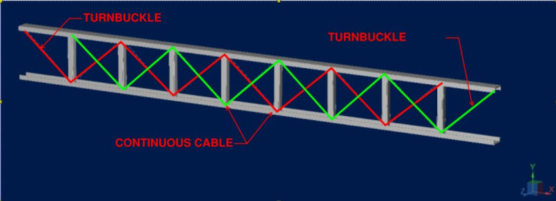
For the cable concept, I think you'd need some form of pretension to mitigate the issue identified by Lo. Maybe you could do the whole thing out of two separate continuous cables, each with a turnbuckle introduced at the end:

CABLE_TRUSS_yfzvyd.jpg


JoshPlum mentioned something about a collapsible joist for shipping. You could combine the ideas here - top/bottom chord pre-assembled with the verticals and the whole thing could fold down. Run the cables through the truss on site and tension it into its final shape.

I love these off the wall ideas...but to maybe keep this grounded a little bit, keep in mind that eventually it just becomes cheaper to pay for heavier framing and use a hot-rolled beam instead of a novel joist idea.
 
A couple super-quick, maaaaaybe not totally thought all the way through comments on the steel cable diagonal ideas:

1) You'd definitely want to pre-stretch the cable before rigging it into the truss (this should eliminate all the cable seating that produces so much relaxation in the cable).

2) From an analysis perspective, individual cables w/in each panel is MUCH easier. A continuous cable will have to have the same tension no matter where on the span it is.

3) I'm not creative enough for any good ideas re: how to make the continuous cable have the correct bend radius at the verts. Maybe you could fish a thimble through the pair of holes that you'll need in the HSS?
 
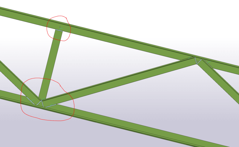
kipfoot, I agree the span in the example is too short for a WT chord design. I think field fabrication will be a very significant challenge. If there jig is not level or square you will end up with a bowed truss. Welders use a lot of clamps when everything is loose. I was trying to lower the part count and keep the parts simple. I pasted a view of a typical joint below. The model was done in Tekla. We have been using that since 2007, and that took about 1hr or so.

TRUSS-3_su4utw.png


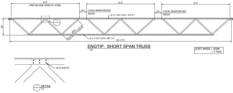
Another idea popped in mind based on the other ideas. I do not think it works, but I pasted the image below anyway. The idea behind this was to use hilti shots to fasten the webs to the chords. The web is fabricated out of plate steel and it would need to be fabricated off site. The shape would allow the CNC operator to nest the webs, but there is still quite a bit of waste. To make the webs work I expect one would need to add stiffeners to the plate similar to how the wood truss guys do. More hilti shots.

TRUSS-4_un3ckm.png
 
I say we make it entirely out of Unistrut and let the electrical guys spec and field assemble them.
 
I work on projects in Mexico pretty often. Our friends south of the border whip together site fabricated trusses on a regular basis, both when the design calls for trusses as well as an alternate to OWSJ's on the drawings. The primary driver for this is material availability and cost. Getting your hands on joists or deck in Mexico has been a challenge in the past, even pre-Covid. In Mexico, the mantra is material is expensive and labor is cheap whereas in the US, its just the opposite. As such, welders in Mexico will give you CJP's over fillets all day without blinking an eye. Now, the dirty little secret is that their willingness to increase the labor comes at a price. Its not unheard of to have what we would consider scraps and cutoffs CJP'd together to make longer members. Similarly, they will CJP weld 3 plates together to make a wide flange or weld 4 plates together to make an HSS. My point to all of this is the following. I get the impression that many of those who responded above are not familiar with the notion of site fabricated trusses. While not common in the US, it is quite common in Mexico and I suspect other countries that may have limited access to resources. That said, I am very interested in the creative and innovative concepts people come up with. (I have seen a few unorthodox, "creative" attempts to make site fabricated trusses, most would make any reputable engineer cringe)
 
I humbly present to you The Jericho

EDIT*************************

The Jericho program has been scrapped. I was watching Charlie Wilsons War with my partner and couldn't enjoy the movie. All I could think about was how labor intensive my pre-fab is on this monster. I realized in trying to steer away from kipfoot's WTs I made it a worse version of KootK's. I will resubmit shortly (kinda like the 5 second rule)

Though I'll leave it up mostly as a historical curiosity but also because I think the bearing design is kinda sexy.

END EDIT*****************

Reading note: Before you tell me that I've called up only fillet welds...when probably less than half are true fillets. I know but it was easy and I have to get on with my life lol!

Competition Note: I'll pony up an additional $50 USD for the cause. Under the condition that I may need to design / build a bridge overtop a repair area in an underground parking garage in the coming weeks and the dream team here must participate!

Capture_jubbci.jpg
 
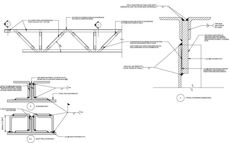
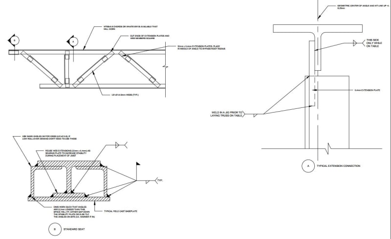
Resubmission attempt: Jericho Reborn

Pros
1 - All standard welds from easy to access locations on material that any fabricator would be familiar with
2 - There is so much room for slop since the fabricator can effectively put the webs anywhere along the length
3 - Truss assembly happens from one side only
4 - Painting is a breeze either shop or field
5 - Can be made from re-used material with plates made thicker to suit eccentricities involved

Cons
1 - Cutting the WT is more labour intensive than buying two angles. But you save on other aspects of the welding that are now super clean/easy.
2 - Heavy for small spans though a larger WT would probably take care of that

Capture_un9ww1.jpg


Link (note that this is the correct new version):
 
JoshPlumSE said:
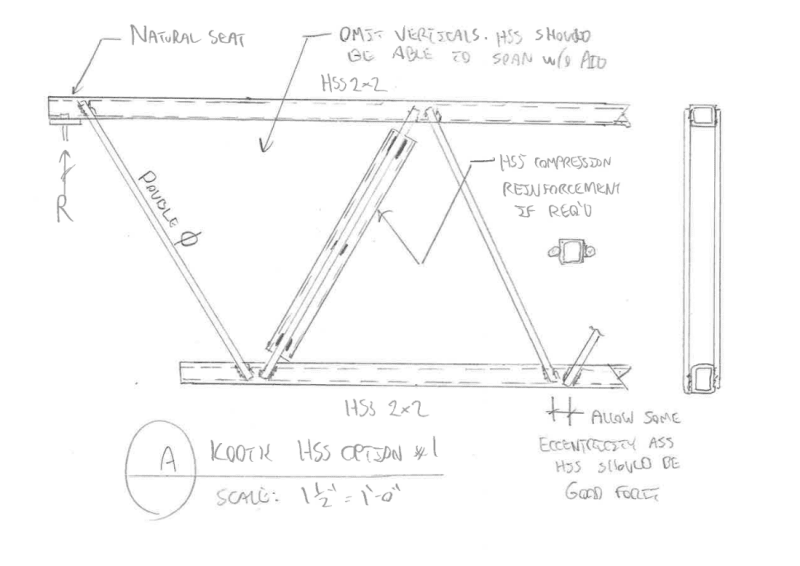
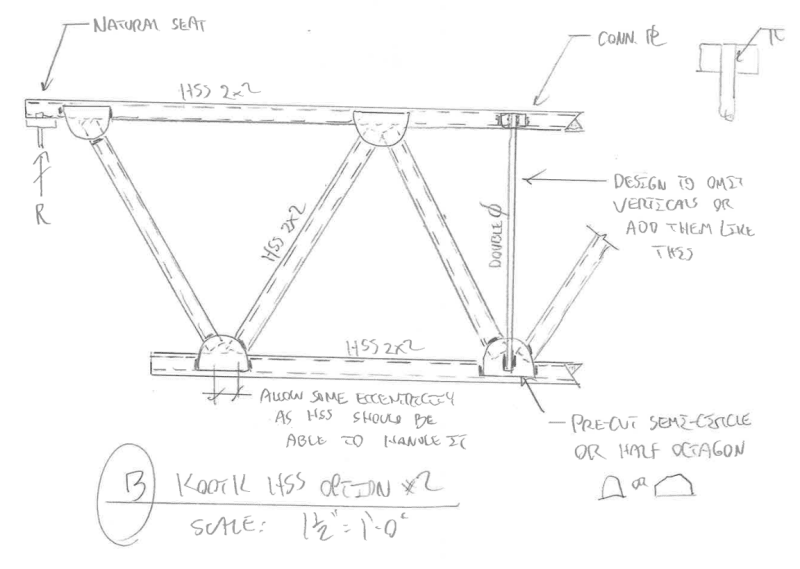
My mind also keeps returning to the idea of using HSS tubes instead of WT's and Single angles and such. I know they're currently more expensive, but they also make really good trusses. Plus, architects and owners love the look. Maybe they'd be less prone to construction damage or erection accident.

Fundamentally, I feel that there must be at least one viable option for each type of steel cross section that provides the following:

1) Small scale section without post-processing.

2) Section provides flat surface for deck attachment.

So my mind keeps returning to some HSS option. I've proposed two options below.

PROS

- Natural seat can just be the tube itself. Add a bearing plate if bolting is desired.

- Tubes should be strong and stiff enough to span between primary panel points without intermediate verticals.

- Tubes should be strong and stiff enough to allow for some degree of panel point eccentricity.

CONS

- Heavy, particularly my second option.

- My first option troubles me with respect to the potential for unequal loads in the webs on either side of the truss.

- For the rod option, I don't love the idea of potential quality control problems with respect to the flare bevel welding.

FABRICATION PLAN

a) Set out the HSS.

b) Weld on the rods or gusset plates to on side.

c) Flip and weld the other side, CANPRO be damned.

END

If I were to order DIY OWSJ on Amazon:

1) I'd probably have to go with dold's corrugated thing because that's screws and I don't know how to weld in real life.

2) If I could weld, I feel that my option B below would probably be my most likely candidate for success.

C01_cck7qw.png


c02_t32da9.png
 
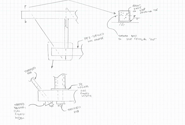
Maybe optimize it with light gage HSS in the 12 - 16ga range and screwed connections.
 
KootK said:
I somewhat rescind that. With the WT setup, I'd actually be fine with single webs hopping back and forth across the WT web. What's a little torsion between friends / panel points...

sbisteel said:
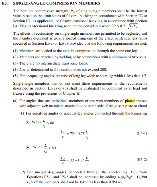
AISC disagrees, and E5.a in the specification actually calls for the webs to be connected to the same side.

Thanks for joining in the conversation and for drawing our attention to E5.a. I disagree with your interpretation however. I think that the correct interpretation is this:

1) Attach your webs to the same side of the chord if you want to be able to avail yourself of some design simplifications.

2) Attach your webs where you like if you explicitly design them for eccentricity sans design simplifications. The Full Monty as it were.

In the case of kipfoot's truss, I'm sure that we can all agree that:

a) The torsion generated across the thickness of the WT web would be minimal and;

b) The torsion from (a) would likely be easily rectified by the out of plane stiffness of any practically sized, incoming angle webs.

C01_k2lyhs.png


c02_cjvosa.png


c02_brf20r.png
 
XR250 said:
Maybe optimize it with light gage HSS in the 12 - 16ga range and screwed connections

If you go one step further to cold-formed tubes, you can get pretty light trusses -- and welding CFS (even flare bevels) is almost trivial, because it doesn't take a lot of weld material to match the base material capacity at 1.5mm thickness.

I had one such truss with double chords and single webs. Doesn't technically need to be flipped, since you can reach any overhead interior weld with a stick pretty easily. (I actually had purlins above, so I was able to make most of the connections work just by having the webs stick through the chords by 10mm and welding above and below the chords).
20190611_113016_ienunh.jpg
20190716_092922_u8pa1t.jpg


----
just call me Lo.
 
That HSS sketch gives me an idea for possibly a cleaner "unistrut" solution...

EDIT... kind of a goof, the roof deck isn't going to sit on this one


Capture3_pig6eg.png
 
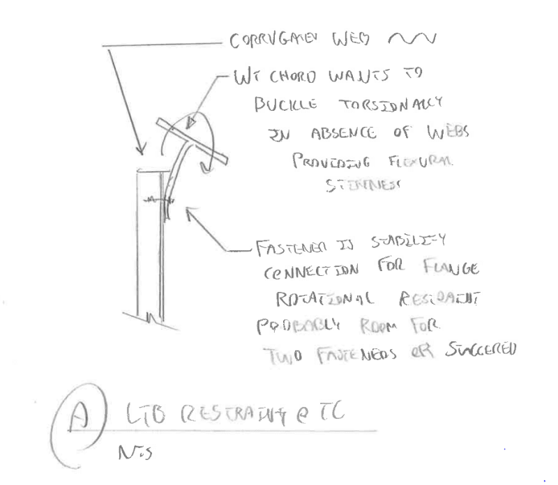
@dold: I have the concern show below for the corrugated scheme. In a normal truss with discrete webbing, the flexural stiffness of that webbing is relied upon to torsionally brace the flanges and keep their unbraced LTB length from being the entire length of the truss. For your scheme the corrugated sheet and its fasteners will have to do that same job in a distributed fashion. There is a load path available to provide this resistance, as shown below, but it's something that I feel warrants some degree of explicit attention and, ideally, testing.

C01_kcwx04.png
 
KootK,

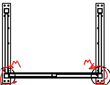
Is your buckling concern during fabrication? Erection? Installed and in service? I had assumed that we could assume a roof deck to brace the top chord out of plane buckling.

The only time I've depended on web members to prevent out of plane buckling on a truss' top chord is when designing a hand rail truss (local term, also known as a pony truss or half-through truss). Part of getting that to work, is that the web members generate a moment resistance at the bottom (see the snip below). For a roof truss, I'm not seeing how the bottom chord could possibly develop a resisting moment with the web members to brace the top chord.

HR_Truss_Cross_section_xvq9ga.png
 
Status
Not open for further replies.

Part and Inventory Search

Sponsor