Continue to Site

Eng-Tips is the largest engineering community on the Internet

Intelligent Work Forums for Engineering Professionals

  • Congratulations GregLocock on being selected by the Eng-Tips community for having the most helpful posts in the forums last week. Way to Go!

Centroid of this compression block - Column Design - concrete - Biaxial bending 4

Pretty Girl

Structural
Nov 22, 2022
84
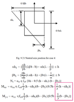
This is from "Reinforced concrete design to eurocodes" by prab bhat, page 367.
I'm bit confused of how did they determine that this five faced shape has the centroid of 1/3 of the shape's height and breadth.
I feel like they just assumed it's a triangle although the pointy ends are truncated.

I see this as inaccurate to calculate the centroid as we can't be sure the faces of this 5 faced shape (compression block) will be proportional always and the imaginary pointy parts (which extends to the outside of the compression block) of the triangle having same area and size. If it's having the same area, the assumption of the book could be almost correct, but still not entirely correct.

Am I correct or wrong?

If the book has wrong method to find the centroid of this compression block, what are the correct formulas (if any) to find it directly, or your suggestions to find out the centroid of this 5 faced shape.

(the relevant formula part of this problem is highlighted with a pink box below)
Screenshot 2024-11-30 at 10.49.27 pm.png
 
Replies continue below

Recommended for you

Pls look to the explanation for this case .This is copy and paste from the same page;

The five-sided stress block shown in Fig. 9.21 can be considered as compression
over the entire column cross section with tension in the triangular area in the left
hand bottom corner. Compression over the entire column does not give rise to any
moment. Moment is caused purely by the tension in the triangular area.
 
@HTURKAK Thank you for the response.

But isn't it inaccurate to assume (consider) the entire cross section in compression? because take the case where the 0.9beta of each side just entered the >b and >h. Thats like half the column cross-section in compression, that gives rise to moment for sure isn't it. It's the very end that the entire cross section is in compression all other in-between cases give rise to moment.

Further, I don't understand why they even consider the small triangle if it's in tension as that calculation is about moment calculation in the compression block. The moment only disappears at the very end, 99% of the section the moment is there.
 
It doesn't assume the entire section is in compression. The triangular area is treated as having a compressive force and an equal and opposite tensile force, so the net force on the triangle is zero, and the centroid of the combined forces is the centroid of the pentagonal stress block.

You could divide the actual compressive stress area into a rectangle and two triangles, and that would give the same result.

Thank you for the response.

The results are close but not accurate.
Is the following calculation wrong?


Given Dimensions:

1. Total Rectangle:
- Height (h): 11
- Base (b): 8

2. Small Triangle:
- Height (α h₁): 4
- Base (β b₁): 3

---

Manual Method: Divide the Pentagon into a Rectangle + Triangle

Step 1: Areas of Shapes
1. Rectangle Area (from the bottom to h - α h₁):
A_rect = b × (h - α h₁) = 8 × (11 - 4) = 8 × 7 = 56

2. Triangle Area (small triangle on the top):
A_tri = (1/2) × β b₁ × α h₁ = (1/2) × 3 × 4 = 6

3. Total Area of the Pentagon:
A_pent = A_rect + A_tri = 56 + 6 = 62

---

Step 2: Centroids of Shapes
1. Centroid of the Rectangle :
- Horizontal (x_rect):
x_rect = 0.5 × b = 0.5 × 8 = 4
- Vertical (y_rect):
y_rect = 0.5 × (h - α h₁) = 0.5 × 7 = 3.5

2. Centroid of the Triangle :
- Horizontal (x_tri):
x_tri = (1/3) × β b₁ = (1/3) × 3 = 1
- Vertical (y_tri):
y_tri = h - (2/3) × α h₁ = 11 - (2/3) × 4 = 11 - 2.67 = 8.33

---

Step 3: Combine Centroids Using Weighted Average
1. Horizontal Centroid (x_pent):
x_pent = [(A_rect × x_rect) + (A_tri × x_tri)] / A_pent
x_pent = [(56 × 4) + (6 × 1)] / 62
x_pent = (224 + 6) / 62 = 230 / 62 ≈ 3.71

2. Vertical Centroid (y_pent):
y_pent = [(A_rect × y_rect) + (A_tri × y_tri)] / A_pent
y_pent = [(56 × 3.5) + (6 × 8.33)] / 62
y_pent = (196 + 49.98) / 62 = 245.98 / 62 ≈ 3.97

---

Method in the book (From the Screenshot I shared in the first post):

Step 1: Horizontal Centroid:
x_approx = [b × (2 α h₁ + h)] / [3 × (α h₁ + h)]
x_approx = [8 × (2 × 4 + 11)] / [3 × (4 + 11)]
x_approx = [8 × 19] / [3 × 15] = 152 / 45 ≈ 3.38

Step 2: Vertical Centroid:
y_approx = (1/3) × [(α h₁² + h² + (α h₁ × h)) / (α h₁ + h)]
y_approx = (1/3) × [(4² + 11² + (4 × 11)) / (4 + 11)]
y_approx = (1/3) × [(16 + 121 + 44) / 15]
y_approx = (1/3) × [181 / 15] = 181 / 45 ≈ 4.02

---

Final Comparison:
| Method | x_pent | y_pent |
|-----------------------------------|--------|--------|
| Manual (Rectangle + Triangle) | 3.71 | 3.97 |
| Approximation (Screenshot) | 3.38 | 4.02 |
 
You are using the wrong shapes; you need to think about what they represent.

If the rectangle had a uniform load creating unit stress over the whole area the force would be 88 and moment about the centre 0.

Now imagine the bottom left corner is cut, and that section of load lifted off. The force would be 5x7/2 = -17.5
The moments about the rectangle centroid are:
Mx = -17.5 x (4-5/3) = -40.83
My = -17.5 x (5.5-7/3) = -55.42
The position of the centroid of the net force is then
Xc = 4 - (-40.83/(88-17.5)) = 4.579
Yc = 5.5 - (-55.42/(88-17.5)) = 6.286

These are not approximations, they are the exact coordinates of the centroid of the rectangle with the bottom left 5x7 triangle cut off.

Thank you.

As I see it also considered the relative distance from centroid of rectangle to the centroid of triangle. Can you pls explain why did we use relative distance?

I'm asking this because as I know, the centroid is defined as sum of all the weighted averages of the elements of the shape and in that centroid distances are taken as distance from the base etc, one common axis for all the elements.
Is it possible for us to use the distances to the centroids from the bottom of the triangle or top of the rectangle for both triangle and rectangle (the distances will be from one common axis), without using the relative distance?
 
I don't know what you mean by "relative distance". All the moments are taken about the centroid of the rectangle, and I have taken the origin as the bottom left corner of the rectangle, so the rectangle centroid is at 4, 5.5. The triangle is 5 wide and 7 high, so the triangle centroid is at (4-5/3), (5.5-7/3).
 

Part and Inventory Search

Sponsor