ecFem
New member
- May 19, 2023
- 19
Hello,
I hope you are doing well.
I started using FEMAP a couple months ago. Before I used HyperMesh as pre-processor.
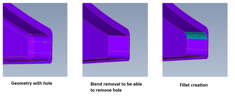
I am doing some geometry cleanup, more precisely, removing a hole. The problem is that the hole was in the intersection of two surfaces (a fillet). Consequently, when I tried to remove it, it changed the whole geometry. Thus, I removed the fillet (with the appropriate tool), I could remove the whole, and then I did again the fillet (cf. image below).

My problem is that the fillet surface appears now with another color, and the same for its edges. I do not understand why is this happening and what the new colors mean (mainly the lines, bc line color in HyperMesh means different things).
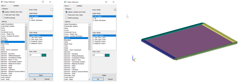
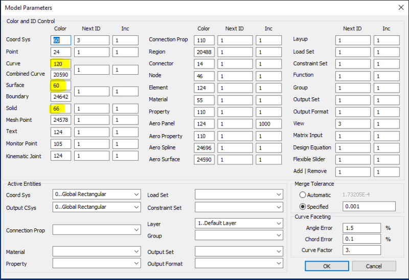
I would like to know if there is a logic behind the color of the lines / solids, and if is there a way to change it (as I have seen I can change it for properties, elements, materials, etc) for geometric elements individually, (lines, surfaces, solids). In other words, to select a component and change its color, not the color for all the solids or surfaces or lines.
Thank you very much in advance.
Cordially,
EAC
I hope you are doing well.
I started using FEMAP a couple months ago. Before I used HyperMesh as pre-processor.
I am doing some geometry cleanup, more precisely, removing a hole. The problem is that the hole was in the intersection of two surfaces (a fillet). Consequently, when I tried to remove it, it changed the whole geometry. Thus, I removed the fillet (with the appropriate tool), I could remove the whole, and then I did again the fillet (cf. image below).

My problem is that the fillet surface appears now with another color, and the same for its edges. I do not understand why is this happening and what the new colors mean (mainly the lines, bc line color in HyperMesh means different things).
I would like to know if there is a logic behind the color of the lines / solids, and if is there a way to change it (as I have seen I can change it for properties, elements, materials, etc) for geometric elements individually, (lines, surfaces, solids). In other words, to select a component and change its color, not the color for all the solids or surfaces or lines.
Thank you very much in advance.
Cordially,
EAC


