Continue to Site

Eng-Tips is the largest engineering community on the Internet

Intelligent Work Forums for Engineering Professionals

  • Congratulations KootK on being selected by the Eng-Tips community for having the most helpful posts in the forums last week. Way to Go!

Column Design - concrete - Biaxial bending 3

Status
Not open for further replies.

Pretty Girl

Structural
Nov 22, 2022
60
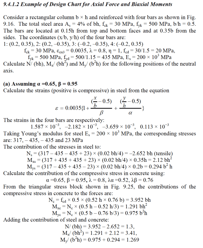
I'm trying to understand the concept behind this bi-axial bending calculation. This is from "Reinforced concrete design to eurocodes" by prab bhat, page 368.
I'm bit confused of how the coordinates are calculated for this. For instance, the book states "The bars are located at 0.15h from top and bottom faces and at 0.35b from the sides" and it says b =0.5h.
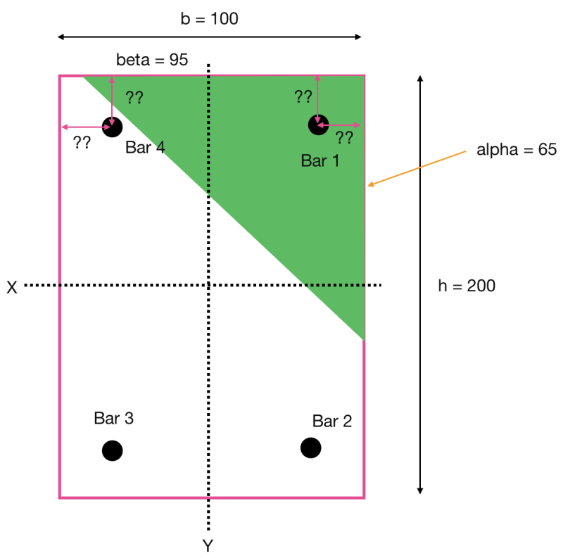
That means, if we assume the b as 100 mm the height is 200 mm. Now if we try to calculate the distances from top and sides,

If we consider the statement "0.15h from top and bottom faces and at 0.35b from the sides"
right side and left side = 0.35b = 0.35 * 100 = 35 mm
top and bottom distance = 0.15h = 0.15 * 200 = 30 mm

Further it has stated coordinates as (0.2, 0.35)
If we consider that,
the left and right distance = x/b = 0.2, so x = 20 mm.
top and bottom distance = y/h = 0.35, so y distance = 70 mm

So, it confuses me as 35 not equal to 20 mm, neither 30 mm equal to 70 mm.

which one is correct?
If the 35 and 30 mm calculation is correct, then the cordinates of (0.2,0.35) are incorrect isn't it? so the entire strain calculation is incorrect in this book?

If the calculation of the book is incorrect, can you please provide the way to get the strain of each four bars for biaxial bending? I'm trying to create the N-M graph for column design. I referred this book because it aligns with eurocodes and I like the simplicity of the calculations although it's confusing sometimes.
Screenshot_2024-06-08_at_8.42.03_PM_oi8onb.png


Screenshot_2024-06-08_at_8.57.23_PM_c3wiis.png
 
Replies continue below

Recommended for you


Assume the coordinates are correct .Apparently there is a mistake (maybe typo ) at 0.35b
The correct para. will be ;
9.4.1.2 Example of Design Chart for Axial Force and Biaxial Moments Consider a rectangular column b × h and reinforced with four bars as shown in Fig. 9.16. The total steel area As = 4% of bh, fck = 30 MPa, fyk = 500 MPa, b/h = 0.5.
The bars are located at 0.15h from top and bottom faces and at 0.10b from the
sides. The coordinates (x/b, y/h) of the four bars are:
1: (0.2, 0.35), 2: (0.2, –0.35), 3: (–0.2, –0.35), 4: (–0.2, 0.35)
fck = 30 MPa, εcu3 = 0.0035, λ = 0.8, η = 1, fcd = 30/1.5 = 20 MPa,
fyk = 500 MPa, fyd = 500/1.15 = 435 MPa, Es = 200 × 103 MPa
Calculate N/ (bh), Mx/ (bh2) and My/ (b2h) for the following positions of the neutral
axis.
...


He is like a man building a house, who dug deep and laid the foundation on the rock. And when the flood arose, the stream beat vehemently against that house, and could not shake it, for it was founded on the rock..

Luke 6:48

 
The bars are located at 0.15h from top and bottom faces and at 0.10b from the sides

I really don't see the point of using these factors in a worked example, rather than specifying the actual values, but if the transverse position of the bars is +-0.2b they are 0.4b apart, so the offset from the sides must be 0.6b/2 = 30 mm for the example shown, i.e. the same as the offset from the top and bottom faces.

Doug Jenkins
Interactive Design Services
 
@HTURKAK
Thank you. I decided to ignore both the 0.15h and 0.35b mentioned in the question.

Further, isn't the following part of the equation for the distance to r/f bars from the y axis? So shouldn't they be equal? But if I use the given coordinates I get different distances.
Screenshot_2024-06-09_at_12.12.01_PM_ezirvy.png


For example: If we consider bar 1 and bar 4, and if we consider the given coordinates for those bars(0.2, 0.35)(-0.2, 0.35),
For bar 1: (x/b) - 0.5 = 0.2/1 - 0.5 = 0.3
For bar 4: (x/b) - 0.5 = -0.2/1 - 0.5 = -0.7

0.3 does not equal to 0.7. They should be in the same distance from y axis and should be having same strains as well shouldn't they? but their strains are also different.
Bar 1 strain: 1.587 x 10^-3
Bar 4 strain: 0.113 x 10^-3

1.587 is not equal to 0.113. Why? Is the strain calculation also incorrect?
 
@IDS
I also think the same. They have made the example more confusing.
 
Why would Bar 1 and Bar 4 have the same strain? The neutral axis is not parallel to the X axis, so there is variation in strain in the x direction.


Doug Jenkins
Interactive Design Services
 
@IDS
You're right, let's say strain can be different, but why x/b - 0.5 would be having different values? shouldn't it be like "+0.3" and "-0.3" as the "x/b - 0.5" should be the relative distance to y axis from reinforcement?

I'm trying to understand the equation mentioned in the book in simple manner. Shouldn't it be the following for the bar 4?

Screenshot_2024-06-09_at_6.10.39_PM_jfg1su.png
 
Pretty Girl said:
as the "x/b - 0.5" should be the relative distance to y axis from reinforcement?

No, we need the distance from the top right hand corner (the point of maximum strain) to the reinforcement, because alpha and beta are measured from that point. Note that the strain will always be reducing, so the dimensions are all negative.

For bars 1 and 4:
For example: If we consider bar 1 and bar 4, and if we consider the given coordinates for those bars(0.2, 0.35)(-0.2, 0.35),
For bar 1: (x/b) - 0.5 = 0.2/1 - 0.5 = -0.3
For bar 4: (x/b) - 0.5 = -0.2/1 - 0.5 = -0.7

The strains calculated in the example in the OP are correct.


Doug Jenkins
Interactive Design Services
 
@IDS
Thank you for the explanation.
Now I understand. So, it should be the "distance from extreme compression fibre for each axis".
 
Status
Not open for further replies.

Part and Inventory Search

Sponsor