Eng-Tips is the largest engineering community on the Internet

Intelligent Work Forums for Engineering Professionals

column k value 2

Status
Not open for further replies.

wag2483

Structural
Oct 28, 2009
11
0
0
US
Attached is a PE sample problem. The answer is B, not following why. All else equal wouldn't the pin/brace direction have k=1.0, while the pin/moment direction has k=0.7. Thus column capacity is less in the brace (north-south) direction and will govern?
PXL_20240809_210826108_3_mvhlbp.jpg
 
Replies continue below

Recommended for you

If it were a truly fixed end reaction at the top of the column (no displacements, no rotations), then yes, k would be 0.7. However, since it has a moment connection (not a fixed-end), your k value will be greater than 1 -> because the beam-column connection in the moment frame has nothing preventing sway at the top of the column.

Please note that is a "v" (as in Violin) not a "y".
 
I also just try to think rationally. There's negligible induced moment in the north-south direction because of the concentric braced frame. But in the north-south direction, you're intentionally putting the column into bending. Axial load being equal, a column with moment always buckles before a column without.
 
All the above answers are correct unless somebody is too pedantic. Thought I would suggest that it is better to think of this problem in terms of stiffness of restraints. And I will choose to be somewhat pedantic....

-Sideway is prevented and inhibited by the moment connections, so pedantically some comments above are not quite accurate. If it wasn't prevented the structure would not be stable.

-The moment comment directly above is mostly true but isn't really directly relevant to buckling. Buckling primarily a stiffness problem. When it comes to axial buckling the induced moment isn't exactly the issue it is the stiffeness of the restraints.

To quickly summarise. The moment frame in Grid 1&2 is vastly less stiff than a braced frame in Grids A & B. Thus when the columns are loaded; [B. 'Buckling in the east-west direction will control column capicty']

Did I mention that I'm aware my comment here is pedantic? [bigsmile] But I do think that it is best to emphasise that controlling of bucklig is a very much a stiffness issue.

 
Disagree with most or all of the replies so far. LOL.

In the N-S direction, the braced frame has a hinged connection at each end of each brace and at each end of the beam. Thus, the column K = 1.0.

In the E-W direction, the moment frame has a sway buckling mode. For those, 1.0 <= K < infinity as shown in the AISC Spec. Commentary Figure C-A-7.2. Unless the beam has an utterly enormous EI, K > 1.0.

Thus, east-west buckling will control.
 
wag2483 said:
while the pin/moment direction has k=0.7.

Looking at the AISC Spec. Commentary Table C-A-7.1, that would be true only if the buckling mode has sway inhibited and the beam had infinite EI. Neither is true.

Looking at this table will lead you the wrong way. Look at the alignment chart stuff that follows.
 
Moment frame is 2.0, braced frame is 1.0. Anyone who has designed a Piperack knows this.

There is a more exact calculation of K using a graph but since the OP doesn't have member sizes then you can't calculate it.
 
Cheers for attaching the graphic in line.

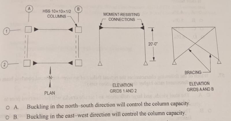
I would challenge this kind of question. It's not remotely clear (to me) that the bases are pinned. (I know a lot of drawings will show a pin this way, but I'm looking for that hollow circle at the base where the column joins the triangle, it isn't like this is an accepted or formalized graphic standard anyway). Or a statement that says "pinned bases" for both directions.

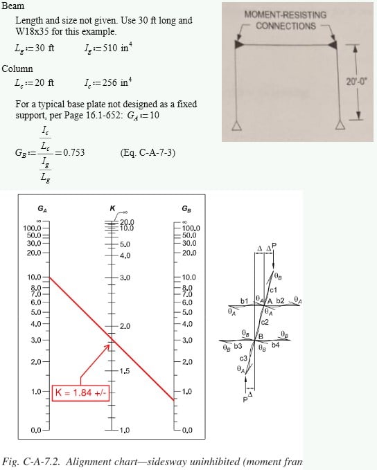
The moment direction will probably control because the HSS column has no "weak axis", and this is an unrestrained case where the frame can deflect at the top (versus the braced frame), so in the idealized case, K=2 for that direction, if the beam is infinitely stiff, which it won't be.

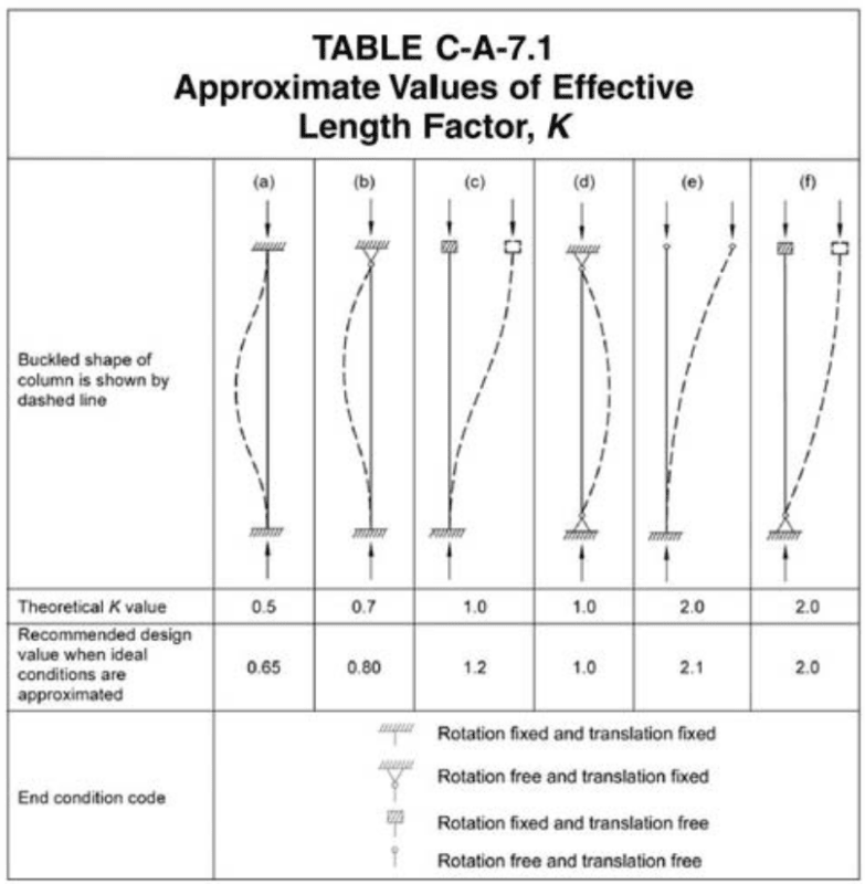
That table works just fine but you are case (f), not case (b), and case (b) is non-sway and fixed base, which is usually not justifiable or not bothered with.
 
"Be careful. There is no upper limit on K for a sway uninhibited mode. It could exceed 2.0. probably won't, but it could. "

You are way overthinking this. We are talking about the OP post and it's clearly a 2.0 in E-W direction. I already mentioned there is a graph to calculate this exactly in real projects where you know the member sizes.
 
How is it clearly 2.0? It would be 2.00 if the base is treated like an ideal frictionless pin and the girder has infinite EI.

Otherwise, K needs to be determined from the alignment chart as shown in the following. K comes out to be < 2.0 but that's just due to the lengths and MOIs chosen in the calcs. Note that if I had used the theoretical pinned base G[sub]A[/sub] = infinity, K would've been greater than 2.0.

Picture1_soqzhb.jpg
 
K = 2.0 for sidesway uninhibited would only be true for the last column in his figure. Column "f." That figure only applies if the top of the column can't rotate, i.e., if the girder EI is infinity. If there is a regular beam at the top, then it is just plain wrong to use that entry in the table.

K can be all the way to infinity for sidesway uninhibited. I have seen values quite a bit above 2.0.

Respectfully, you guys are scaring me with how you interpret this stuff.
 
Nobody even use K because everyone uses direct analysis method. Maybe in slenderness check.

Nobody is saying K can't go more than 2.0 in real projects where you know all the information and can calculate it in more exact.

Scaring you? You are over dramatic.
 
"I would challenge this kind of question. It's not remotely clear (to me) that the bases are pinned."

@Lexpatrie It doesn't matter because it's the same symbol both directions. K<=1.0 vs K>1.0 either way.
 
AsktooMuch said:
"Be careful. There is no upper limit on K for a sway uninhibited mode. It could exceed 2.0. probably won't, but it could. "

You are way overthinking this. We are talking about the OP post and it's clearly a 2.0 in E-W direction. I already mentioned there is a graph to calculate this exactly in real projects where you know the member sizes.

I'll just cheer myself up that you're not designing anything critical that affects life-safety with that flippant little inaccurate comment.

You cannot achieve 2.0 K factor in this situation unless you have an infinitely stiff beam. If you'd said it was over 2.0, I'd have kept quiet. But the 2.0 "It's clearly 2.0" is totally wrong.

It WILL exceed 2.0.
 
Lex, it's clearly 2.0 based on olddawg post of approximate K. And that's what I and other engineers I know use for "initial" K of moment frame during preliminary design.

And you're totally wrong about the beam need to be infinitely stiff to have 2.0 or lesser K. Just look at "271828" example. It has 1.84 K for just W18 beam.
 
Status
Not open for further replies.
Back
Top