271828 said:
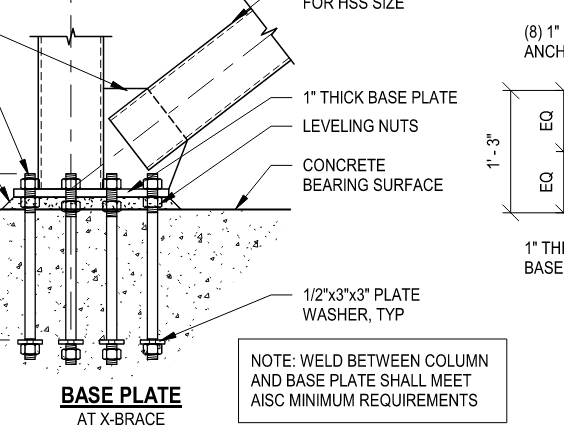
Usually the vertical component of the brace force is taken by the gusset-to-HSS column welds, which then gets transmitted to the base plate through the HSS-to-base plate welds. There's a chance this force could be large.
Not really on the topic here, but I don't think this is very correct. The HSS load goes into the gusset, the gusset transfers the vertical load (plus) via the weld into the face of the HSS, and the lateral load (plus) into the base plate- UFM. You could probably design it the way you describe, taking the entire load as tension, shear, and bending into the column via the gusset, and arrive at a safe design via some sort of upper bound/lower bound argument, but I don't think that's a typically used load path. It's been a while since I did delegated connection design and that was R=3 anyway, so not seismic, effectively.
Night School 6, Session 2: The Uniform Force Method, Thornton, AISC, 2014
Designing Compact Gussets with the Uniform Force Method, Muir, AISC Eng. Jour, 1st quarter, 2008, currently a free download as of 7/6/24.
Given the nature of this "connection" it suggests to me this could be in a significant seismic zone, at which point the connection design gets a good deal woolier.
I still think this is a cloud by the detailer. "EOR provide weld size" - e.g. Refuse to size this weld and ask for confirmation. Force the EOR to actually provide the design, and ideally, via a revision cloud on the detail, and on the sealed revision 1 plans.....
These sort of coordination problems will proliferate if people other than the engineers don't hold the "our" feet to the fire. This isn't proper connection design procedure, it isn't proper delegated design procedure, and it needs to get at least a little horse medicine (cause the horse pain to diagnose the problem, because if it's the problem it's extremely painful, not just uncomfortable, and you know what the problem is...)
As the detailer has stated, they aren't doing engineering here, and the forces are not disclosed so they physically cannot size the weld (nor could a connection design engineer, unless they want to go the "maximum force the connecting elements can possible endure" approach). At least the work point is where it's supposed to be.