I’m looking for some advice on finalising the hydraulic design on a cable tensioning system.
Four Cylinders are being used to pull a 160 strand cable to 1274t tension over approx. 840mm stroke, the cylinders are 300mm bore x 200mm rod x 700mm stroke. Buckling is ok.
From 0mm to 700mm the load goes to approx. 200te, the next 140mm is stretching the cable and the force rises exponentially to 1274t.
When the cylinder runs out of stroke or the final tension is realised a large jacking nut is threaded down the cable onto a bearing plate, the problem is that in order to install the cable (offshore) the cable is installed with this 840mm slack which as is passed through a U shaped inclined clamp. When the job is done two opposing cable cross in an X shape so the cable end mounting plates are fixed approx. 45 degrees. When we install the slack cable the catenary weight causes the bearing plate to tilt 8 degrees in the mounting plate, analysis has shown a force of 200t is required to rotate the bearing plate.
Link
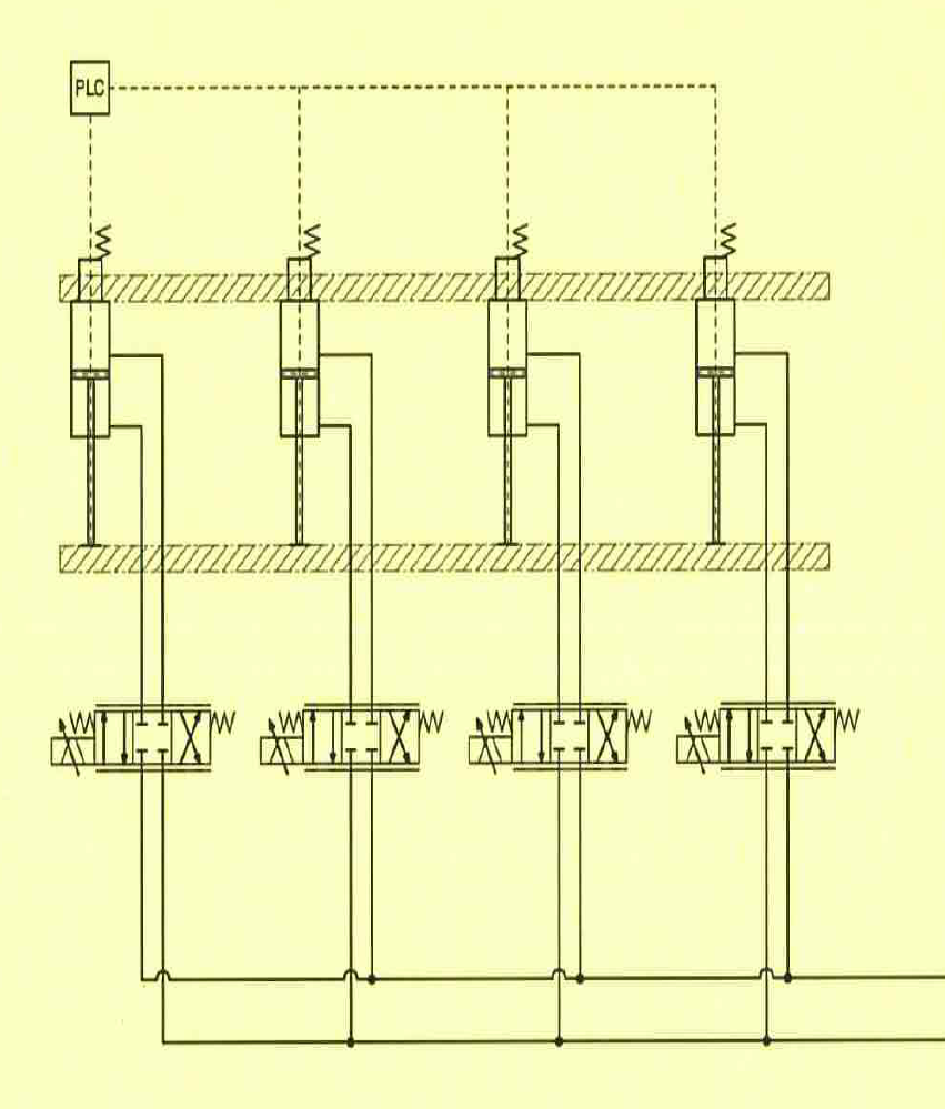
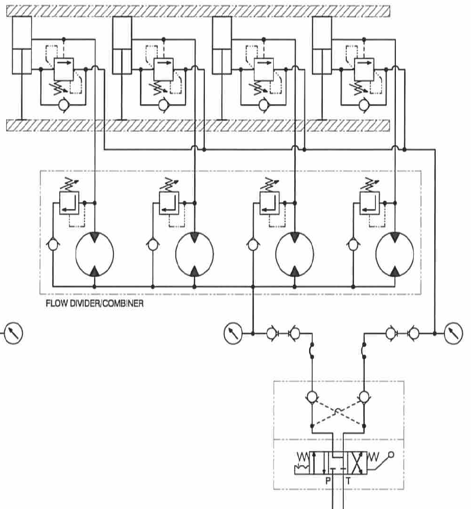
In order to prevent thread damage it is important to ensure the cylinders all extend in unison, to complicate matters the two cylinders furthest away from the corner of the bearing plate in contact with the clamp are being put under tension “dragging” the rods out of the cylinder (see att. where the hatching indicates high pressure in the cylinder due to the induced load), the two cylinders adjacent to the contact point are being compressed. The hydraulic design must accommodate this up the c.200t load after which the 8 degree gap between the bearing plate and clamp is closed and the force applied by the four cylinders push in the same direction. Various concepts for this control are being considered from individual servo control of each cylinder to the use of an over centre valves with a single directional valve and flow divider, both concepts have yet to be considered fully.
If we pursue a solution with servo or proportional valve controlling each cylinder with each having a feedback loop fed from cylinder mounted distance transducers this could give us a problem. Any error correction in one cylinder will have an effect on the adjacent cylinder as they are all rigidly connected to one another via the jacking plate (cross head), this could give rise to a confused system that may be impossible to operate.
I’m also considering a simplified solution of over centre valves (as shown) in the annulus side of each of the cylinder and piloting open from the full bore, the load induced is approx. 15t equating to 37 bar in the annulus.
I’ve discussed with the leading Servo valve people and they are very nervous of the problem noted above.
Any help would be appreciated.
Regards
escapizm


