Eng-Tips is the largest engineering community on the Internet

Intelligent Work Forums for Engineering Professionals

Complex Hydraulic Synchronising Problem 3

Status
Not open for further replies.

escapizm

Marine/Ocean
May 14, 2013
40
0
0
GB
I’m looking for some advice on finalising the hydraulic design on a cable tensioning system.

Four Cylinders are being used to pull a 160 strand cable to 1274t tension over approx. 840mm stroke, the cylinders are 300mm bore x 200mm rod x 700mm stroke. Buckling is ok.

From 0mm to 700mm the load goes to approx. 200te, the next 140mm is stretching the cable and the force rises exponentially to 1274t.

When the cylinder runs out of stroke or the final tension is realised a large jacking nut is threaded down the cable onto a bearing plate, the problem is that in order to install the cable (offshore) the cable is installed with this 840mm slack which as is passed through a U shaped inclined clamp. When the job is done two opposing cable cross in an X shape so the cable end mounting plates are fixed approx. 45 degrees. When we install the slack cable the catenary weight causes the bearing plate to tilt 8 degrees in the mounting plate, analysis has shown a force of 200t is required to rotate the bearing plate.
Link
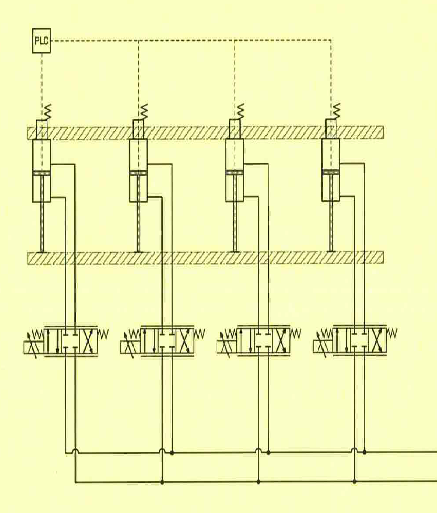
In order to prevent thread damage it is important to ensure the cylinders all extend in unison, to complicate matters the two cylinders furthest away from the corner of the bearing plate in contact with the clamp are being put under tension “dragging” the rods out of the cylinder (see att. where the hatching indicates high pressure in the cylinder due to the induced load), the two cylinders adjacent to the contact point are being compressed. The hydraulic design must accommodate this up the c.200t load after which the 8 degree gap between the bearing plate and clamp is closed and the force applied by the four cylinders push in the same direction. Various concepts for this control are being considered from individual servo control of each cylinder to the use of an over centre valves with a single directional valve and flow divider, both concepts have yet to be considered fully.

If we pursue a solution with servo or proportional valve controlling each cylinder with each having a feedback loop fed from cylinder mounted distance transducers this could give us a problem. Any error correction in one cylinder will have an effect on the adjacent cylinder as they are all rigidly connected to one another via the jacking plate (cross head), this could give rise to a confused system that may be impossible to operate.

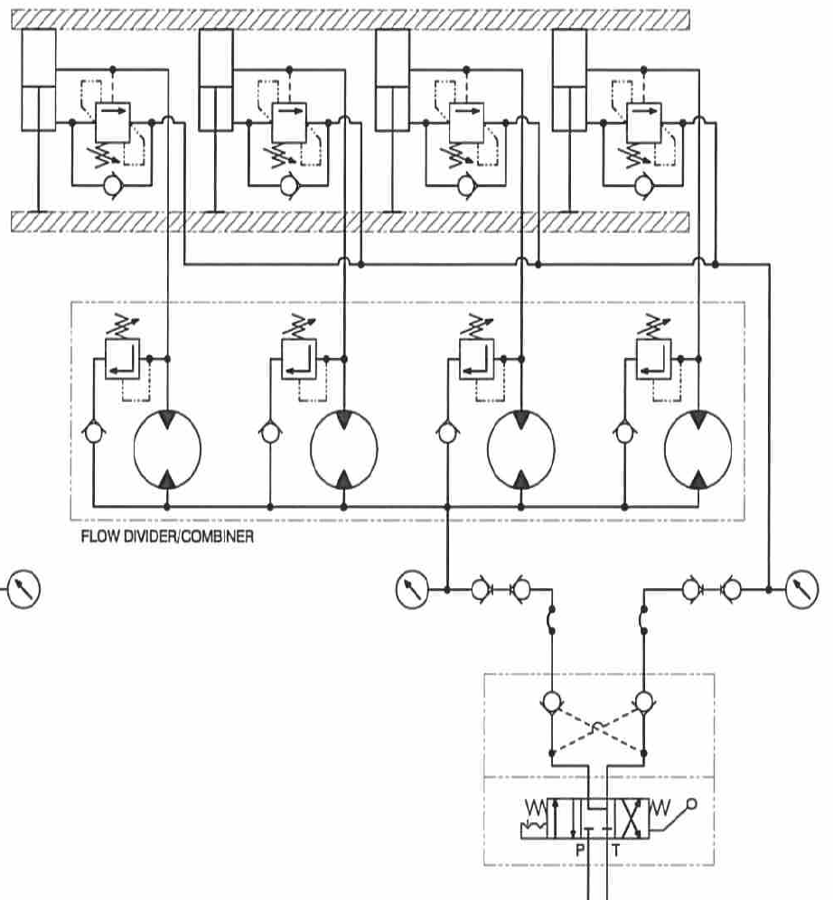
I’m also considering a simplified solution of over centre valves (as shown) in the annulus side of each of the cylinder and piloting open from the full bore, the load induced is approx. 15t equating to 37 bar in the annulus.

I’ve discussed with the leading Servo valve people and they are very nervous of the problem noted above.

Any help would be appreciated.

Regards

escapizm
 
Replies continue below

Recommended for you

From experience of servo and proportional controls V flow divider...I would suggest going for a flow divider.

Use 1 flow divider...ideally from Slack and Parr in the UK.

Use a directional control valve for each cylinder that you want to operate.

If you want to drive 4 cylinders, use a four channel flow divider and 4 DCVs.

Use over centre valve to hold the cylinders still and use double rod cylinders (if you have room) to keep the same speed in both directions. Don't use a flow control valve to control speed because even pressure compensated valves have a pressure drop that will cause leakage across the flow divider and will put the cylinders out of sync.

This set up works perfectly well in many marine applications where cylinder synchronisation is paramount. It is very robust.

Regards

Adrian

 
Thanks Adrian

What are the benefits of 4 DCV's instead of 1 into the flowdivider? Ive used 1 in the past.

Did you see the link to my circuit?

Regards

escapizm
 
Yes I did see the link...

There are good reasons for using 4 DCVs.

1) It gives you synchronised flow in both directions
2) It means that you don't have to use the flow divider as a flow combiner, the tank lines from the DCVs go around the flow divider.
3) When using as a flow combiner, if the cylinders are not mechanically linked, it is possible to drive one cylinder on its own. With uneven loading on the cylinders the lightest loaded cylinder will tend to move first. With no oil coming in from the heaviest cylinder, the gear in the flow divider will turn in air.

It is more expensive to have 1 flow divider and 4 DCVs, but the payback is long service.

The system I designed uses this set up. There is a fleet of USCG cutters...all of their boat davits use this hydraulic system.

Cheers

Adrian
 
HI Adrian

Sorry to be a pain…

My system is rigidly connected with all four cylinders attached front and back via rigid crossheads within a 1.5m cube (albeit without sides), the cylinders stroke 700mm.

I can’t quite grasp what the benefits of individual valves feeding into separate section of the flow divider are. I would of put a DCV with 4 times the capacity feed one section as shown below.

Service life is of minor concern, the cylinders are going to stroke once or twice until we achieve maximum tension then the whole hydraulic system is going to be removed and possibly never used again!

Also, am I right in thinking despite the uneven initial loading due to the mechanics of the machine that by installing the over centre valves the cylinders will see an even load and thus equal pressure drop in each section of the flow divider. Uneven pressure drop could lead to the cylinders extend out of sink, although the rigidness of the system will aid this I think.

circuits here
servo_zps30ccbdfd.png
overcentre_zps9af2ddaa.png


Regards,
 
Go with that then...if the cylinders are mechanically linked, there will be no problem.

If you use a decent flow divider, you'll get good performance out of it.

Your schematic shows proportional directional control valves, that would be proper expensive. Do you need accurate position control?

What are the PO check valves for?

Adrian

 
HI

Precision* is of major importance and one consideration prior to my joining the project was servo or proportional valves, the Servo people had reservation with it working due to that mentioned in my first post so i came up with the other solution. The system operates very slowly stroking approx 700mm in 30mins to 1 hour. The system may also be left mid or full stroke as such i dont want spool leakage to permit the cylinders to come down thus the PO check.

*This is why i asked about the over centre valve and flow divider leakage.

Thanks
 
The over centre valve holds the oil in the cylinder, there will be no leakage across the spool. You don't need the PO checks, they are not doing anything.

The divider will only leak when it's operating.

To reiterate, the over centre valves will stop the oil coming out of the cylinder so the internal leakage on the other system components can be neglected.

The flow dividers Slack and Parr make are super accurate, they are derived from dosing pumps and they are very precise.

A proportional DCV with a flow divider and cylinder position feedback to close the loop should work a treat.

Cheers

Adrian
 
This problem is easy to solve if you use servo control. What you need is something like the automatic leveling found in some advanced presses.
The automatic leveling control will keep your cylinders synchronized even though the loads on the cylinders are uneven.

escapizm's application is very slow compared to a press. escapizm's applications should be easy of the hydraulic design is good.

I don't see how a flow divider will work unless the synchronization specification is very lax. The oil will compress a lot with long cylinders.

A lot depends on the specifications and your tolerance for risk. The flow divider idea may work well enough but the servo control will work.


Peter Nachtwey
Delta Computer Systems
 
It's this sort of activity that makes me want to stop my contribution to this forum.

I give honest and open support and ideas based on real experiences to give a cost effective and robust solution to a problem.

Peter, it is not appreciated when you give advice that contradicts and undermines the advice I have given, which as I say, is based on real applications involved with life saving and mission critical systems in harsh marine environments.

Nobody doubts that servo control will solve the problem, but there are aspects of servo control that make it somewhat tricky to purchase, set up and maintain.

I was giving balanced advice, please don't come in a late stage and dismiss or undermine my advice. As I said...it is not appreciated.

Adrian
 
Well, oops all over me. I intended that as a Red Flag comment.
Attribute it to what motorcycle racers call "brain fade".
... and everybody have a cup of tea. Please.


Mike Halloran
Pembroke Pines, FL, USA
 
hydromech said:
It's this sort of activity that makes me want to stop my contribution to this forum.

I give honest and open support and ideas based on real experiences to give a cost effective and robust solution to a problem.

Peter, it is not appreciated when you give advice that contradicts and undermines the advice I have given, which as I say, is based on real applications involved with life saving and mission critical systems in harsh marine environments.

Nobody doubts that servo control will solve the problem, but there are aspects of servo control that make it somewhat tricky to purchase, set up and maintain.

I was giving balanced advice, please don't come in a late stage and dismiss or undermine my advice. As I said...it is not appreciated.

Adrian

What is the point of an open forum where anyone can contribute if only one person is allowed to express their opinion? This is an engineering advice forum, not your own personal consultation.
Whilst I agree with you on this, it really isn't fare to dismiss other peoples opinions because they differ from yours. If you really want to, just rationally explain the pros and cons of both ideas. Multiple ideas for solving a problem is always better than one.
 
Can people not read...?

My opening comment was to state that, from experience of both options and from the info given...a flow divider gives the most cost effective solution to the apparent problem. It was a piece of balanced advice. My objection to Peter's approach was that it came late on is the conversation that was, as I see it reaching a conclusion. The original post had indicated that a servo control solution was not preferred. There seemed little point advocating servo control, let alone being so dismissive of my comments.

All are free to add their own opinion and advice, but, as is often the case, people weigh in with unhelpful and misguided advice simply because they did not read the thread fully.

I always read each thread thoroughly to make decision on whether I can make an alternative point or support someone else's advice. I would expect other professional engineers to do the same.

People need to read what is there before contributing!!!

I'm off for a cup of tea...
 
The simplest solution is just the rigid crossheads, of course.
... PROVIDED that the associated bearings are long enough to not lock up.

Predicting whether that will happen is a sophomore kinematics problem.
... that we lack data to solve, but given the stated envelope,
I'm guessing that binding is possible to some extent.
So flow dividers make sense. I'd suggest that they be sized to spin relatively fast, so internal leakage won't affect their performance so much.
I'll bow to Adrian's experience about the flow divider source and the number of directional control valves.

As for the servos, beyond the innate complexity, I think the crossheads would need to be articulated so that the cylinder/transducer units could move independently of each other, _or_ the transducers would need extraordinary resolution so that each servo loop would be mostly independent of the others.
I'd also be troubled by having four (delicate) servovalves on a piece of heavy duty rigging, so I'd want to build an armored cage around them, adding weight and cost. ... to a device that may be used just once.
I'm not saying servos wouldn't work, just that they wouldn't be my first choice for this job.


Mike Halloran
Pembroke Pines, FL, USA
 
I posted to supply an answer that I know will work. It is for escapism to decide which way to go, not hydromech.

Nobody doubts that servo control will solve the problem
Well now escapizm has his answer then. A servo control system will be more expensive but the risk is smaller because a servo valve will adapt for the compression of the oil column and leakage.

, but there are aspects of servo control that make it somewhat tricky to purchase,
Purchasing just cost money.

set up and maintain.
It only has to work for a short while. Get an expert to set it up. This looks like a it is a small part of a big project and it would probably cost a lot to screw it up.

My objection to Peter's approach was that it came late on is the conversation that was, as I see it reaching a conclusion.
I was waiting for the specifications and an estimate of how much skew there would be. I saw no calculations for the estimated skew. The skew will increase as the load increasing due to compression of the oil. Skew will increase over time because of leakage. How much leakage will their be with the best flow dividers over 30 minutes of moving time.

With no calculations or specifications I would say it is iffy if a flow divider would work.
As far as costs go. How much does failure cost?

All are free to add their own opinion and advice, but, as is often the case, people weigh in with unhelpful and misguided advice simply because they did not read the thread fully.
I read it thoroughly. What is misguided about my advice? Why isn't it helpful?

Predicting whether that will happen is a sophomore kinematics problem.
... that we lack data to solve, but given the stated envelope,
This applications seems like a slow one, 30 minutes or more, where kinematics aren't a problem. The problem will be how much the oil columns will compress under load and how much the oil will leak if the move takes a long time.

quote]
As for the servos, beyond the innate complexity,
[/quote]
To an expert, servos are not complex.

I think the crossheads would need to be articulated so that the cylinder/transducer units could move independently of each other, _or_ the transducers would need extraordinary resolution so that each servo loop would be mostly independent of the others.
I doubt the Beckwood press cylinders are articulated yet the press must accomplish much the same goal. The link I posted says the press control can handle uneven loads. I have actually been there and seen it in action. The total force of the press is probably much less than 1247t but the press is much faster and must react to uneven loads in milliseconds. These press machines use servo control to do the automatic leveling day in and day out stamping thousands of strokes per day! escapism needs only to do a few strokes.

_or_ the transducers would need extraordinary resolution so that each servo loop would be mostly independent of the others.
The resolution of MDT rods is now down to micros which makes little difference in this application because of the forces involved. The metal will probably stretch or compress 10s of microns.

I'd also be troubled by having four (delicate) servovalves on a piece of heavy duty rigging, so I'd want to build an armored cage around them, adding weight and cost. ... to a device that may be used just once.
The press provides plenty of shock and the valves survive. Again, escapizm's system only needs to work once.

I would like to know who escapizm's servo people are.
It will be interesting to see which way escapizm goes and how his project works out.
This forum is technophobic.


Peter Nachtwey
Delta Computer Systems
 
Peter,

It's not technophobia, it's balanced and free advice based on experience. I for one do not have a company to promote, in particular a company that has much to gain in advocating electronic control.

I am fully aware of the full benefits of PID control with proportional or servo control. I am also aware of the costs and fragility of the said systems.

If you get the chance, have a look at the code of conduct for Chartered Engineers as part of the Institute of Mechanical Engineers. That will explain my motives.

By all means, work as an advocate of servo control to support you business interests, but please don't be so quick to dismiss the ideas of your fellow engineers.

I apologise for detracting from the theme of the original question.

Cheers

Adrian
 
It's not technophobia,
Yes it is.

it's balanced and free advice based on experience.
No it isn't. Your prejudice has been revealed by using the word fragile over and over again. See below.

I for one do not have a company to promote, in particular a company that has much to gain in advocating electronic control.
I didn't mention my company. It is simply in my signature.

I am fully aware of the full benefits of PID control with proportional or servo control.
Well maybe.

I am also aware of the costs and fragility of the said systems.
I object to your choice of the word fragile. Hydraulic servo controls is being used in very nasty environments like oil and gas, wood processing, steel mills, lifting sections of bridges, nuclear material handling, packing power into shells, and even gantry control for rocket launchers.

but please don't be so quick to dismiss the ideas of your fellow engineers.
At first I only offered an alternative with a question about flow dividers meeting the specifications and this question still hasn't been answered.

We get involved with a few unique application like this one. This project looks like it is part of a big construction project. A simulation would be good for a proof of concept. It may take a few days but it might save time and money in the end. It would want to minimize risk.


Peter Nachtwey
Delta Computer Systems
 
Folks, thanks for the debate!

Some clarity on the above.

Given the rigid nature of my existing (huge casting was purchased months ago) crosshead and the possible uneven loading along one edge, MOOG (the leaders IMHO) suggested the analysis/simulation to determine how the system would operate and the subsequent design of the software and programing could be as expensive as the valves alone. If I was to go with servo control of each cylinder individually that would require 24 servo valves plus digital controllers as there are 6 systems as my circuits. The valves would be stainless steel to handle the pressure and are made to order with a total package price of c. GBP £179,000 plus any analysis and programing!!! Let’s say GBP £360K for a temporary installation aid and this is not for an ATEX Exd Zone 2 system as I’ve now discovered the system must be adding another 10% perhaps.

If I have confidence in parallel operation (+/- 10mm over 700mm stroke) of the jacking plates with the flow divider this is my favoured solution, I can increase the speed of operation but would be nervous of moving such massive loads quickly, if gear leakage is an issue on the smallest high pressure flow divider I can find I may well increase the speed. The load is only uneven up to c.200t after which it becomes even across all four cylinders as the cable becomes taut. 70 Bar in the full bore gives me 50t in each cylinder so I can get the 200t with plenty in hand, we will prove the system at FAT before we procure the full quota.
 
As a bench mark, a Slack and Parr flow divider gave a position differential of 3% across 2 cylinders at 18MPa and stroke range of 1800mm.

I couldn't get a better performance from any other device, but I could have paid more to have gears ground to match the housing to minimise the clearance.

Good luck

Adrian
 
Status
Not open for further replies.
Back
Top