Continue to Site

Eng-Tips is the largest engineering community on the Internet

Intelligent Work Forums for Engineering Professionals

  • Congratulations cowski on being selected by the Eng-Tips community for having the most helpful posts in the forums last week. Way to Go!

Composite callout

Status
Not open for further replies.

aniiben

Mechanical
May 9, 2017
165
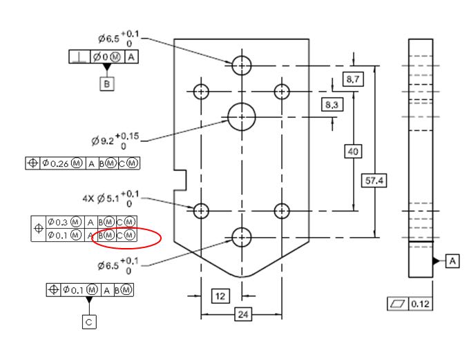
Does the addition of B secondary and C tertiary in the lower segment of the composite (FRTZF) brings any value to the callout? If yes, what is the value added?

What would be the differences between only A primary shown in the lower segment (FRTZF) on the composite versus what is shown on the embedded picture and circled in red?

CC_kyj4zl.jpg
 
Replies continue below

Recommended for you

3DDave,
Could you expand on how you would apply datum targets to a FOS such that it would act in a similar manner as a FOS datum? I would think that would work over B(M)-C(M) I'm just not sure what it would look like.

Evan,
That was something that always irked me on the CDRF section - it seems like such a complex topic that was added as an afterthought with a few short paragraphs and examples that don't even begin to give proper guidance on how the CDRF tool is utilized with datum feature simulators and the like.

Before I go too deep into asking questions, I want to understand exactly what you mean by "special behavior" of the datum feature simulators - could you describe exactly what kind of behavior you believe is necessitated/allowed by CDRF and how its supported by the standard?

Also per 3DDave's post I wonder if there could be certain situations where a CDRF is specified where the combination of geometry and behavior of the datum feature simulators cannot be replicated accurately by physical simulators and could only exist in the digital realm.
 
greenimi,

Yes, the main difference between Bill's interpretation of composite lower segments and my interpretation is in how the "orientation but not location" property of the lower segment is achieved. Bill's article desribes it in terms of the datum features constraining only rotational degrees of freedom, and I would describe it in terms of the tolerance zone translating. As far as which interpretation is "right" and which is "wrong", I'm not sure that there is a simple answer to this.

The problem is that the standard includes elements of both interpretations. If you go through all the text and figures on composite position and composite profile (which I have, many times), I would say that some of it supports the "datum features control only rotational DOF's" interpretation and some of it supports the "zone translates" interpretation. There is also a lot of material to wade through that doesn't give any clues (examples in which the lower segment datum feature is only capable of controlling orientation anyway). If you look in textbooks, most authors paraphrase what Y14.5 says about the lower segment zones, without explaining it further.

I agree that the lack of clarity makes things very difficult for the average user. It makes things difficult for GD&T experts! I've talked to several committee members, trainers, and consultants over the years about composite FCF's and I have not found a consensus as to how the lower segments work. So what do we do? We have to figure out the tolerance zone behavior that Y14.5 was trying to define, and judge for ourselves which theory describes it in the most workable way.

Evan Janeshewski

Axymetrix Quality Engineering Inc.
 
Status
Not open for further replies.

Part and Inventory Search

Sponsor